This thread has been locked.

If you have a related question, please click the "Ask a related question" button in the top right corner. The newly created question will be automatically linked to this question.

TLV320AIC3104: TLV320AIC3104 output abnormality

Part Number: TLV320AIC3104

Tool/software:

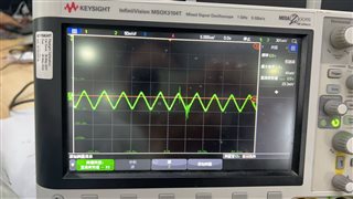
When playing a 1KHz single sound source, the codec output waveform is as follows. Please help me find out what the reason is. Thank you.

  • Hi,

    I notice that your SPK1 and SPK2 may be connected incorrectly, RIGHT_LOM and RIGHT_LOP will be one (-) and (+) differential pair of line outs to SPK1, and LEFT_LOM and LEFT_LOP will be the pair to SPK2. Potentially your issue we are seeing is due to the scope/speaker trying to take a differential pair of two very similar signals.

    Let me know if switching these connections helps.

    Best,
    Mir

  • Are you saying there is something wrong with the testing method?

  • Hi,

    Your schematic looks to be connected incorrectly at the outputs. You confused L/R with P/M outputs. It may not be an easy fix with the measurements because of the filters you have. I drew out the lines showing which output goes to which speaker, note that blue=right output, and purple=left output:

    Let me know if this fixes your issue.

    Best,
    Mir

  • hi,

        Please see the latest schematic diagram, the connection is correct,thanks!

  • Hi,

    This looks better! Let me know if you are still having issues with the device.

    Best,
    Mir

  • HI,

    The schematic diagram has always been correct. The one uploaded earlier may not look clear because the signal was not pulled apart, but the problem has always existed. Please help me continue to analyze it. Thank you!


  • Hi,

    Okay, we can figure this out. Can you also attach your i2c config or register dump?

    Thanks,
    Mir

  •      0  1  2  3  4  5  6  7  8  9  a  b  c  d  e  f    0123456789abcdef
    00: 00 00 00 91 20 1e 00 0a 00 20 00 01 00 00 00 20    ...? ?.?. .?... 
    10: 20 ff ff 00 78 78 00 78 78 06 00 fe 00 00 fe 00     ...xx.xx?.?..?.
    20: 00 00 00 00 00 c0 00 00 40 00 00 0a 0a 2f 2f af    .....?..@..??//?
    30: 00 00 00 0f 2f 2f af 00 00 00 0f 00 00 00 2f 2f    ...?//?...?...//
    40: af 0f 00 00 00 2f 2f af 0f 2f 2f af 2f 2f af 0b    ??...//??//?//??
    50: 2f 2f af 00 00 00 0b 00 00 00 2f 2f af 0b fe 0c    //?...?...//????
    60: 00 00 00 00 00 00 02 00 00 00 00 00 00 00 00 00    ......?.........
    70: 00 00 00 00 00 00 00 00 00 00 00 00 00 00 00 00    ................
    80: 00 00 00 91 20 1e 00 0a 00 20 00 01 00 00 00 20    ...? ?.?. .?... 
    90: 20 ff ff 00 78 78 00 78 78 06 00 fe 00 00 fe 00     ...xx.xx?.?..?.
    a0: 00 00 00 00 00 c0 00 00 40 00 00 0a 0a 2f 2f af    .....?..@..??//?
    b0: 00 00 00 0f 2f 2f af 00 00 00 0f 00 00 00 2f 2f    ...?//?...?...//
    c0: af 0f 00 00 00 2f 2f af 0f 2f 2f af 2f 2f af 0b    ??...//??//?//??
    d0: 2f 2f af 00 00 00 0b 00 00 00 2f 2f af 0b fe 0c    //?...?...//????
    e0: 00 00 00 00 00 00 02 00 00 00 00 00 00 00 00 00    ......?.........
    f0: 00 00 00 00 00 00 00 00 00 00 00 00 00 00 00 00    ................
    

  • Hi,

    Give me a day to look at this, sorry about the delay.

    -Mir

  • Hi, 

    I looked at the register dump, I do not see anything obviously wrong. Can you show where you are measuring this output, and what are you sending to input to the device? Can you explain what the issue is?

    Best,
    Mir

    For reference, here is commented reg dump:

    03 91 #PLL enabled, q=2, p=1
    04 20 #J = 8
    05 1e #111 1000 0000 = D= 1920
    07 0a #left dac plays left channel data, right dac plays right channel data
    09 20 #i2s mode, 24 bits
    0b 01 #r=1
    0f 20 #left adc pga is not muted, gain=16dB
    10 20 #right adc pga is not muted, gain=16dB
    11 ff #mic2l is not connected, mic2r/line2r not connected to left adc pga
    12 ff #lic2l/line2l, mic2r/line2r is not connected to right adc pga
    15 78 #mic1rp/line1rp is single ended mode, line1r is not connectred to left adc pga
    16 00 #mic1rp/line1rp is single ended mode, level control gain =0dB, line1r is conected to right adc pga, powered down
    18 78 #mic1lp/line1lp is single ended mode, line1l is not connected to right adc pga
    19 06 #micbias output powered down
    1a 00 #agc disabled
    1b fe #default max gain for l agc
    1e fe #default max gain for r agc
    25 c0 #left and right dac powered up
    28 40 #output common mode voltage = 1.5V
    2b 0a #left dac channel not muted, gain = -5dB
    2c 0a #right dac chanel not muted, gain = -5dB
    2d 2f #reserved
    2e 2f #pga_L not routed to hplout
    2f af #DAC_L1 is routed to HPLOUT, volume control = 010 1111
    33 0f #HPLOUT level control=0dB,not muted, fully powered up
    35 2f #PGA_L is not routed to HPLCOM
    36 af #DAC_L1 is routed to HPLCOM, volume ctrl = 010 1111
    3a 0f #HPLCOM level control = 0dB, not muted, fully powered up
    3f 2f #PGA_R is not routed to HPROUT
    40 af #DAC_R1 is routed to HPROUT, volume ctrl = 010 1111
    41 0f #HPROUT level = 0dB, not muted, fully powered up
    46 2f #PGA_R is not routed to HPRCOM
    47 af #DAC_R1 is routed to HPRCOM, volume control = 010 1111
    48 0f #HPRCOM level = 0dB, not muted, fully powered up
    51 2f #PGA_L not routed to left lop/m
    52 af #DAC_L1 is routed to LEFT_LOP/M, volume control = 010 1111
    56 0b #left_lop/m output level = 0dB, not muted, fully powered up
    5b 2f #pga_r not routed to right lop/m
    5c af #DAC_R1 is routed to right_lop/m, volume control = 010 1111
    5d 0b #RIGHT_LOP/M level = 0dB, not muted, fully powered up
    5e fe #l+r dac fully powered up, l+r lop/m fully powered up, hpl/hprout fully powered up
    5f 0c #hpl+hprcom fully powered up