This thread has been locked.

If you have a related question, please click the "Ask a related question" button in the top right corner. The newly created question will be automatically linked to this question.

TLV320AIC3101: Rise/Fall time measurement and MCLK requirements

Part Number: TLV320AIC3101

Tool/software:

Hi team,

I would like to double check the points below. 

1: Are these the voltages required for measuring tr and tf?

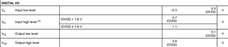
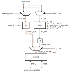
2: Does the Digital I/O parameters' min/max voltages also apply to MCLK?

Best Regards,

Yu

  • Hi Sato-san,

    1) The voltages are related but not directly required. The timing diagram should be measured with 90% and 10% thresholds with respect to IOVDD. However these logic thresholds determine margin of what timing is acceptable.

    2) Yes, digital IO parameters apply to all digital inputs including clocks like MCLK.

    Best regards,
    Jeff McPherson

  • Hi Jeff san,

    Thank you!

    Best Regards,

    Yu

  • Hi Jeff san,

    Are there any requirements on the AC component like rise/fall time and H/L length?

    BR,

    Yu

  • Hi Sato-san,

    The rise fall time, H/L length, etc are dependent on the clocking mode and format used. Respective limits are found in the timing characteristics table.

    Best regards,
    Jeff McPherson

  • Hi Jeff san,

    Sorry I forgot to mention but I meant for MCLK when I said;

    requirements on the AC component like rise/fall time and H/L length

    Table 9.6 shows timing characteristics on BCLK and others, but not MCLK. Does the Master mode details apply for MCLK?

    /

    Also, is the clock tree setting correct for MCLK=24.576MHz, fs=48kHz with PLL disabled? Q=4 setting has an issue where the audio cuts intermittently, and Q=2 has a high noise floor.

    MCLK=24.576MHz

    Q=4

    CODEC_CLK=MCLK*2/Q=12.288MHz

    fs=CODEC_CLK/256=48kHz

    BR,

    Yu

  • Hi Sato-san,

    It's assumed that MCLK is not used in slave mode, but if you are using MCLK in slave mode you can refer to the master mode details for MCLK.

    Yes Q=4 is correct. Q = 2 will create a internal 96kHz sampling which will conflict with the 48kHz I2S clocks and create problems. 

    Intermittent cuts is likely not a clock divider problem. That's usually caused by clock errors, or noise on the data causing the data receiver to lose latching. You can also double check the timing requirements we discussed above. Are you talking about ADC data cutting out, or analog output audio cutting out?

    Best regards,
    Jeff McPherson

  • Hi Jeff san,

    It's assumed that MCLK is not used in slave mode, but if you are using MCLK in slave mode you can refer to the master mode details for MCLK.

    Though not assumed, MCLK can still be used in slave mode? 

    This system is for syncing 3 TLV320AIC3101s together, and minimizing the differences in clock timing discrepancies. Would you instead recommend using BCLK and generating all internal clock by each device's PLL, rather than daisy chaining MCLK on all 3 devices?

    Are you talking about ADC data cutting out, or analog output audio cutting out?

    Let me check.

    BR,

    Yu

  • Hi Sato-san,

    To sync all devices together, I recommend slave mode. MCLK can be used as the internal clock source if available but BCLK can be used to. What matters is that the clock source between the 3 devices is in sync. Though I think using MCLK would be easier in this case since it avoids any timing issues around PLL.

    Best regards,
    Jeff McPherson

  • Hi Jeff san,

    Are you talking about ADC data cutting out, or analog output audio cutting out?

    This is ADC data cutting out. 

    Is there any other information I can provide to you for finding the cause of the issue? (clock signal perhaps?)

    BR,

    Yu

  • Hi Sato-san,

    ADC data dropping out is typically caused by noise on the clocks or incorrect frequencies. I recommend customer double check timing requirements and that the signal does not have obvious noise on it.

    Also if they are already connecting three devices, try only testing one codec at a time to see if the ADC data is stable on one device. Connecting multiple devices to the same clock can introduce reflection errors which require termination resistors to solve. Reflections can be seen on a scope if the clock has jagged edges on the transition edges 

    Best regards,
    Jeff McPherson

  • Hi Jeff san,

    Understood. Thank you!

    If the issue is not fixed, would it be okay to use PLL signal form BCLK as the clock source for all 3 devices? (concern is the natural discrepancies of PLL accuracies across different deices)

    To sync all devices together, I recommend slave mode. MCLK can be used as the internal clock source if available but BCLK can be used to.

    I assume that would be yes, as long as all 3 devices are in sync.

    Br,

    Yu

  • Hi Sato-san,

    You are mostly correct that BCLK can be used as PLL source but I think you are asking about removing the discrepancies of the PLL. If BCLK is 256 * sample rate then yes this is fine. If BCLK is lower then the PLL will be required (or use MCLK).

    Best regards,
    Jeff McPherson

  • Hi Jeff san,

    Just to double check, is it okay to use BCLK+PLL for all 3 CODECs on the board, without the concern of devices going out of sync?

    Best Regards,

    Yu

  • Hi Sato-san,

    If all devices are powered up at the same time and the clocks are all synchronous I would expect all devices to be in sync yes. But it is important that the power up is identical.

    Best regards,
    Jeff McPherson

  • Hi Jeff san,

    Thank you!

    BR,

    Yu