Tool/software:
Hi
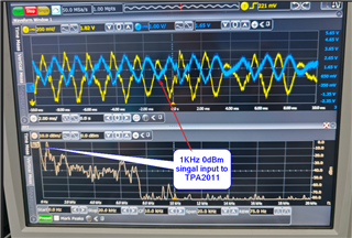
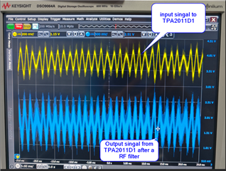
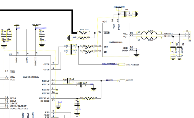
Our product use TPA2011D1, input port serial connected a 10nF capacitor and a 150kohm resistor, to test its output signal, we add a RC circuit, serial connect a 500ohm resistor, parallel connect a 10nF capacitor. Before this RC circuit, we can test square waveform, only when input standard signal range is from 3KHz/0 dB to 4KHz/0dB, after this RC circuit we can test sine waveform, if input signal at other frequency, the waveform will deeply distorted. If no signal input, we also can hear a noise from speaker. Could you help to analyze where our issue is?

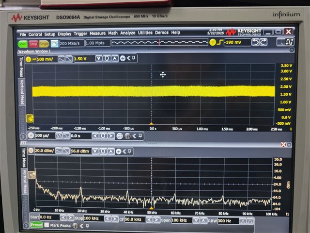
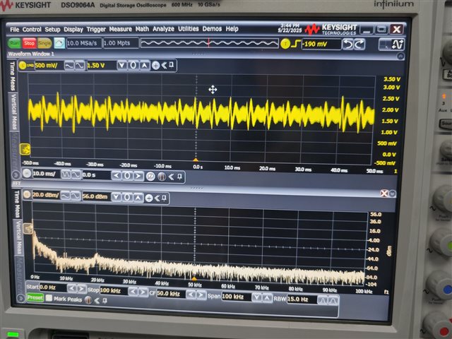
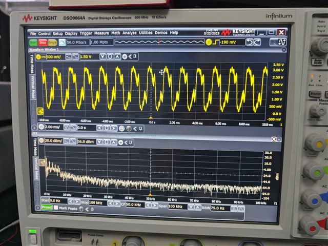
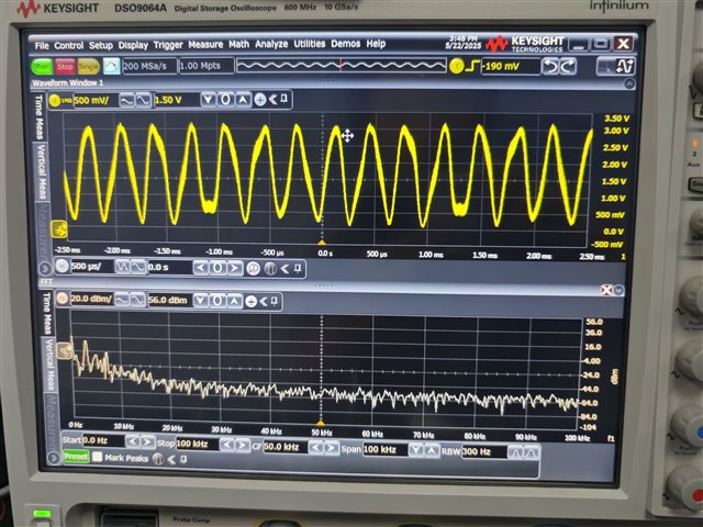

 To test sine waveform, I remove LC filter and add RC circuit.
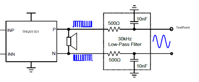 To test sine waveform, I remove LC filter and add RC circuit.
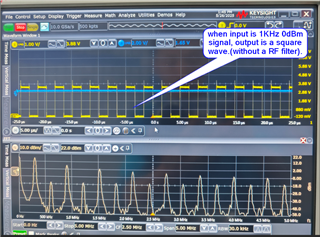 ,
,