Tool/software:
HI,
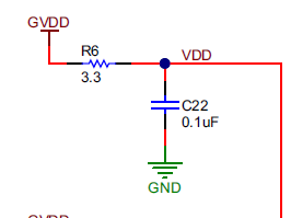
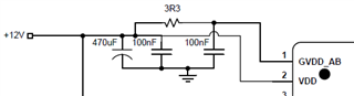
In the datasheet application section (Fig. 25). there is a 3.3 ohm resistor in series with the GVdd pin but in the EVM schematics, the resistor is on the Vdd pin instead. Which is correct?
Thanks!
Tool/software:
HI,
In the datasheet application section (Fig. 25). there is a 3.3 ohm resistor in series with the GVdd pin but in the EVM schematics, the resistor is on the Vdd pin instead. Which is correct?
Thanks!