This thread has been locked.

If you have a related question, please click the "Ask a related question" button in the top right corner. The newly created question will be automatically linked to this question.

LM4675SDBD: LM4675SD Design Query

Part Number: LM4675SDBD
Other Parts Discussed in Thread: LM4675

Tool/software:

Hello TI team,

Please help me with below situation. 

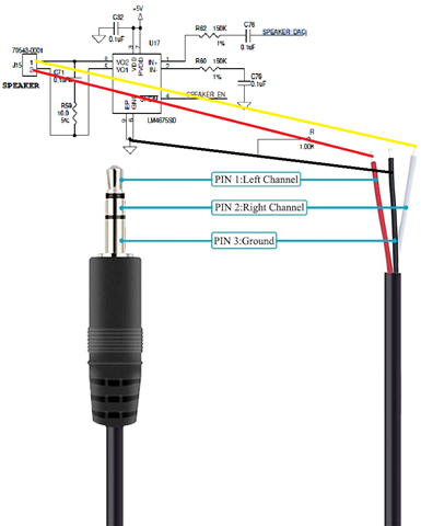
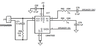
I have a LM4675SD based design, which I am using to drive a speaker. please refer to the snap below for schematics

Now, I want to change it to drive speakers of an external monitor [Stereo].

Below are the specs of audio input port of Monitor

            Audio Input Range: 2.8V pp

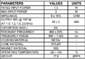
            Speakers with 8Ohm, 0.5W (THD+N=10%) x2

            3.5mm audio jack


     1) How do I make this connection?

     2) Should I electrically short "Left" and "Right" signal on the cable?

     3) How do I take care of ground connection?

      4) Should I use TS cable, as it is mono channel source of audio?    

Please suggest. 

Regards,

Yashwanth

  • Hi Yashwanth,

    Just to clarify, LM4675 is a differential output amplifier, but now you need to drive a single-ended speaker instead? You may try connecting the single-ended speaker to one of the outputs.

    Best regards,
    -Ivan Salazar
    Applications Engineer

  • Hello Ivan Salazar,

    Thanks you for guiding here.

    Here is what I did. 

    Took a audio 3.5mm cable [TRS] and made connection as below.

    connected the plug end to monitor.

    Result: No sound heard on monitor speakers. 

    Am I missing something here? 

    Kindly help me with your thoughts

  • Hi Yashwanth,

    I'm afraid this may mean that the modulation scheme of LM4675 cannot drive a speaker in single-ended connection.
    Just for sake of testing, you may try connecting VO1 to PIN1 and VO2 to PIN3, leave PIN2 floating, check if one of the monitor speaker produces sound, if this works it would prove that LM4675 can only drive the speaker in differential connection.

    You would have to use a separate amplifier for the single-ended connection. Then maybe add a shutdown control toggle for each amp based on the 3.5mm jack connection.

    Best regards,
    -Ivan Salazar
    Applications Engineer

  • Hello Ivan Salazar,

              Here is update. 

               Did the wiring as suggested. [connecting VO1 to PIN1 and VO2 to PIN3, leave PIN2 floating]

               Result: No sound on monitor speakers. [either]

               Here are the waveforms captured ay VO1, VO2 and IN+ signals. 

               If I remove the cable and connect in to onboard speaker, speaker is playing the sound. 

               Am I missing something here?

    Regards,

    Yashwanth

    VO2

             VO2

    VO1

    VO1


    IN+

  • All these measurements are made in a 200MHz Tektronix scope and with a passive probe. 

  • Hi Yashwanth,

    If you measure impedance across PIN1 and PIN3, do you get 8Ohm as the spec you shared at the beginning of this thread?

    Is this monitor speaker a conventional one with magnet and voice coil? or some kind of special transducer that needs DC bias to produce sound?

    Best regards,
    -Ivan Salazar
    Applications Engineer

  • Hello Ivan,

                     I measured the resistance between pins. 

                         Pin1 to Pin3: 10KΩ [Tip/Left to Sleeve/GND]

                         Pin2 to Pin3: 10KΩ [Ring/Right to Sleeve/GND]

                         Pin1 to Pin2: 20KΩ [Tip/Left to Ring/Right]

                   I don't have details of how the audio circuit is internal to Monitor, once it is received at 3.5mm jack. 

                    Based on measurements looks like its not a direct connection to speakers and possibly through an amplifier with 10K termination at input side. 


                   Regarding waveform I shared yesterday, 

                            IN+: ~220Hz (4.5mS period), 800mVpp signal, Square wave signal (Approximately, I did not measure Duty Cycle, but by appearance]. 

                            VO1: ~350KHz (Period 2.8uS), ~7Vpp Signal and kind of PWM in nature

                            VO2: Similar to VO1. 

                  Please help me understand,

                          1) Wrt driving speakers on external monitor through TRS [3.5mm] cable

                                   A) As far as frequency of VO1 is concerned, it is at ~350KHz; How does this signal becomes relevant for audio band?

                                     Possibly input stage filters it out and hence no audio?  

                                   B) Regarding voltage levels, applying 7Vpp audio input, does the input stage gets saturated? [if it is a amplifier] 

                                   As mentioned earlier, 

                                            Below are the specs of audio input port of Monitor

                                                   Audio Input Range: 2.8V pp

                                        Looks like, we are violating both frequency and voltage of audio input and driving to saturation.

                                         Am I missing something here? if so, please correct me         


                                 2) Wrt driving speaker on board [existing design]

                                       below are the specifications of speaker.   


                                      How does this driver work in this situation?

                                           VO1 Frequency, is not a out of band?

                                           Regarding drive levels, how this equation works? Is it Voltage or Current or Wattage? which is influencing / limiting factor? 

                                                 Is applying 7Vpp is right thing?

                                           What is that I am missing here?  

    Regards,

    Yashwanth


  • More waveforms attached. 

    VO1, VO2 and Differential (using MATH function) at different time scales

  • Hi Yashwanth,

    I'll go through your updates and provide feedback Monday next week.

    Best regards,
    -Ivan Salazar
    Applications Engineer

  • Hi Yashwanth,

    1.a The PWM you see at the output of the LM4675 amplifier is expected. Note this is a Class-D amplifier; speakers have a natural low-pass response, so the audio produced and perceived by human ear is only the audible portion of it.

    1.b You may use a low-pass filter (RC or LC) at the output of LM4675. This can help checking the output signal more clearly (removing the PWM modulation) and you could also try using the filtered signal as input to the monitor.

    2. Please refer to both answers above. In order to see the signal that's actually being driven to the speaker, you'd have to add a low-pass filter. Then you can use that waveform to estimate how much power is actually driven to the speaker and the frequency of the signal as well.

    Best regards,
    -Ivan Salazar
    Applications Engineer