This thread has been locked.

If you have a related question, please click the "Ask a related question" button in the top right corner. The newly created question will be automatically linked to this question.

TLV320DAC3100: How to configure the output to a high impedance state

Part Number: TLV320DAC3100

Tool/software:

Hi Team

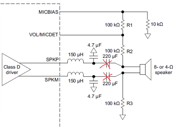
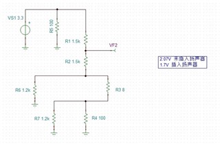
We follow the application to design speaker open load detect circuit.

https://www.ti.com/lit/an/slva824/slva824.pdf?ts=1748246701430&ref_url=https%253A%252F%252Fwww.google.com%252F

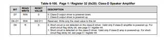
The key to circuit functionality is that the Class D amplifier output of the DAC3100 chip can be configured as a high-impedance state so that the external circuit can determine the speaker status by dividing the voltage.

So I would like to ask, when I power down the class D amplifier, can I configure the output to a high impedance ? Or what is the way to configure the output to a high impedance state?

Thank you very much.

  • Hi Tony,

    When the Class-D output driver is powered down, the pin will be in a hi-z state. 

    Best regards,
    Jeff McPherson

  • Hi Jeff

    Do you make sure it is hi-z state? My customer tested with their current board and found that the result was not hi-z state, could you help with the test on board. Thank you very much.

  • Hi Tony,

    What number did they measure? When the class-D is powered down, the output fets are not biased meaning the output impedance is the off impedance of the fet. This number should be very high. There might be some other body diode/ESD protection diodes involved that keep the impedance measurement from reporting open load, but by design the output driver is high-z when powered down.

    Best regards,
    Jeff McPherson

  • Hi Jeff

    My customer has estimated that the class D amplifier has a pull-down resistance of about 1.2 Kohm to GND by testing the output voltage of the class D amplifier to GND in both power on power down scenarios. This may be due to what causes a non-high resistance state? Can we show a diagram of the chip output part by email?  tony-liu@ti.com

    Also customer would like remove cap and directly connect speaker and class D output. Because the speaker output volume is reduced because the cap takes up a portion of the power. 

    They would like to know if MISBAIS will have leakage current to Class D amplifiers when D amplifier power down, and if there are any risks or effects. Because the cap was removed.

  • Hi Tony,

    Where did this picture come from? Class-D output should never be connected to VOL/MICDET or MICBIAS.

    Those two 220uF caps are not necessary. It is okay to remove those.

    I am not sure if we have easy access to the design files because the device is quite old. As I mentioned there are probably other diodes at play.

    Can I ask what the concern is around the speaker amp having hi-z output when powered down? Is there a leakage current concern?

    Thanks,
    Jeff McPherson

  • Hi Jeff

    Picture is from https://www.ti.com/lit/an/slaa540b/slaa540b.pdf

    which is AN for Class D open load detect.

    Can you explain that after we remove the 220uF capacitance, we can also connect MICBAIS or VOL/MICDET to the Class D amplifier output? What is the risk of such a connection?

    My customer wants to detect if the speaker is open when the Class D amplifier has no output, then is there any other risk when the Class D amplifier is on going output ? How do you suggest we do this?

    The measured impedance abnormality, although different from the high impedance status, it can also be determined by the voltage variation via the DECT pin for external MCU ADC. So the circuit can work, but we want to confirm whether there is a problem, and why the impedance will behave relatively small, as you mentioned the diode problem. So please help with more explanation, thank you.

  • Hi Tony,

    Sorry I misunderstood the application the customer was using. Let me correct my previous information.

    The 220uF caps cannot be removed. They are required to block MICBIAS voltage from contesting with the voltage output of the Class-D driver. The app note also says directly "The 220-µF capacitors are necessary to minimize dc bias of the detection circuit. These capacitors must be large in order to minimize any contribution to the series impedance of the speaker circuit." You can try increasing the cap size if the series impedance is a concern.

    This detection circuit makes a voltage measurement formed by the impedance of the speaker. I believe it will still work even when the amp is on because the pull ups to MICDET are much stronger than the load.

    The measured impedance abnormality, although different from the high impedance status, it can also be determined by the voltage variation via the DECT pin for external MCU ADC. So the circuit can work, but we want to confirm whether there is a problem, and why the impedance will behave relatively small, as you mentioned the diode problem.

    The detection circuit does not rely on the output impedance of the amp because of the DC blocking caps. I do not understand the concern. Please elaborate.

    Thanks,
    Jeff McPherson

  • Hi Jeff

    If customer remove the Cap, and use MUX to switch the Detect circuit and D class output circuit. Is this a good solution?

    When D class amp is working output , MUX will disconnect the Detect circuit.

    And if Detect circuit is working , Mux will disconnect the D class amp.

    Is it working? 

  • Hi Tony,

    We should review the final circuit again after the customer designs it, but in theory yes this will work.

    Best regards,
    Jeff McPherson

  • Hi Jeff

    Customer sch is like: 

    The following illustration is an speaker open load detection circuit, please help review, thank you.
    1, when the normal D class amp output working, the class D amplifier Power on, CTRL_FALL is low power normal, Off-detection voltage circuit is disconnected;
    2, when no sound output state, will do open load detection, the class D amplifier Power off, CTRL_FALL set to high level, As seen from the test results before. when the speaker MICDET is 1.7V ,speak is good connected ; MICDET is 2.07V when the speaker is open load ; and while sounding, we collect the current at the AUD_5V side. to detect if speak working well in system during output sound. Feedback is given by the presence of current.

    Do you think this solution can working? Please give some suggestion if there have some risk. Thank you very much.

  • Hi Tony,

    The mux connection does not look right to me. 

    When normal Class-D output, SPKP_P and SPKM_N are connected to GND. The detection is circuit is removed from the Class-D output. This is fine.

    When Class-D is off and detection needs to be connected, SPKP_N and SPKM_P are connected to GND. The detection circuit is still not connected. SPKM_P needs to connect to SPKM_N and likewise for SPKP_x. I think DGND cannot be the common pin between the switches in the mux.

    Best regards,
    Jeff McPherson