Tool/software:
We are currently in the process of setting up an audio playback environment using the TAS6754Q1EVM.
The evaluation board is connected to a PC via USB, and we are attempting to send audio data via I2S.
[Question]
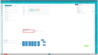
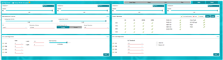
On the PPC3 interface, the sampling frequency is displayed as “FS Error.”
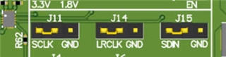
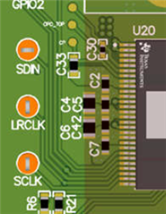
According to measurements taken with an oscilloscope, the LRCLK is operating at 48kHz.
Although no sound is currently being output, it appears that the audio data is reaching the amplifier.
Would you be able to advise on any possible causes of this issue, as well as any recommended countermeasures?
[My test environment]
USB connection between TAS6754Q1EVM and PC (PPC3).
Connect TAS6754Q1EVM and 4ohm Resistor(simulated speaker).
J13: D
J21: USB
J19: OPEN
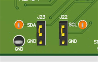
J22:SCL
J23:SDA
Audio data output from PC(foobar2000) via USB