This thread has been locked.

If you have a related question, please click the "Ask a related question" button in the top right corner. The newly created question will be automatically linked to this question.

PCM3070RHBEVM-K: Requesting support for PCM3070 - CODEC Audio Evaluation Board and driver for i2c configurations

Part Number: PCM3070RHBEVM-K
Other Parts Discussed in Thread: PCM3070

Tool/software:

Hi Team,

Currently, we are using PCM3070RHBEVM-K Audio Evaluation Board to generate required sampling rates. 

Required PCM3070 configurations :

  • Codec : Master mode
  • 32 bit width
  • 192,000Hz sampling rate
  • Both Transmit & Receive the audio data to/from DUT.
  • We are using our own i2c controller.

Could you please provide driver code and eval board connections and PLL connections and configurations for 192KHz for above configurations.

Regards,

Pavan

  • Hi Pavan,

    This device does not have a specific Linux driver, but if you wanted to use a driver, the AIC3154 has a driver, and the registers are very similar between the two devices (https://www.ti.com/tool/TLV320AIC32X4SW-LINUX). However, if you have your own I2C controller, then you do not need a driver, as this codec is controlled via I2C. Just make sure that the device is provided an MCLK. I can help you more with specific I2C configuration if you are able to tell me the MCLK rate, since the clocks need to be calculated from the MCLK in master mode.

    Best,
    Mir

  • Hi Mir,

    Thanks for your quick response.

    We need to configure like below:

    codec : master mode

    sampling rate (WCLK) : 192KHz

    PCM data Width : 32-bit

    BCLK : 12.288MHz

    MCLK :  Anything is fine. need to observe above BCLK.

    data directions : Both Tx & Rx.

     please share particular registers to configure above data.

    And one more request, PCM3070RHBEVM-K board connections for both Tx and RX for above configurations if i use my own i2c controller.

    Regards

    Pavan

  • Hi Pavan,

    You can find a few example scripts in the application reference guide: https://www.ti.com/lit/ug/slau332/slau332.pdf

    The configuration of the clocks depends on the MCLK if you are in master mode - you cannot generate the BCLK and WCLK at specific frequencies without knowing the MCLK. But, you could start with 24.576MHz as an example, 2x the BCLK you want. I added a bit to the example for master mode operation and 24.576MHz MCLK, otherwise it is the same code as in the application reference guide for both the high quality DAC output and high quality ADC input.

    w 30 00 00 # Initialize to Page 0
    w 30 01 01 # S/W Reset to initialize all registers
    w 30 0b 81# Power up the NDAC divider with value 1
    w 30 0c 84# Power up the MDAC divider with value 4
    w 30 0d 00# Program the OSR of DAC to 128
    w 30 0e 80
    w 30 12 81# Power up NADC divider with value 1
    w 30 13 84# Power up MADC divider with value 4
    w 30 14 80# Program OSR for ADC to 128
    
    w 30 1b 3c #i2s, 32 bits, bclk and wclk are OUTPUT from the device (master mode)
    
    # FOR MASTER MODE: dac_clk as input to bdiv_clkin, then n=2
    w 30 1d 00 
    w 30 1e 82 #BCLK ndiv = 2
    
    
    w 30 3d 01# Select ADC PRB_R1
    w 30 3c 08# Set the DAC Mode to PRB_P8
    
    # Select Page 1
    w 30 00 01
    
    w 30 01 08# Disable Internal Crude AVdd in presence of external AVdd supply or before powering up internal AVdd LDO
    w 30 02 00# Enable Master Analog Power Control
    w 30 7b 01# Set the REF charging time to 40ms
    w 30 0a 00# Set the input common mode to 0.9V
    
    w 30 3d 00# Select ADC PTM_R4
    w 30 47 32# Set MicPGA startup delay to 3.1ms
    w 30 34 80# Route IN1L to LEFT_P with 20K input impedance
    w 30 36 80# Route Common Mode to LEFT_M with impedance of 20K
    w 30 37 80# Route IN1R to RIGHT_P with input impedance of 20K
    w 30 39 80# Route Common Mode to RIGHT_M with impedance of 20K
    w 30 3b 0c# Unmute Left MICPGA, Gain selection of 6dB to make channel gain 0dB
    w 30 3c 0c# Unmute Right MICPGA, Gain selection of 6dB to make channel gain 0dB
    
    w 30 14 25# HP soft stepping settings for optimal pop performance at power up
    w 30 0c 08# Route Left DAC to HPL
    w 30 0d 08# Route Right DAC to HPR
    w 30 03 00# Set the DAC PTM mode to PTM_P3/4
    w 30 04 00
    w 30 10 00# Set the HPL gain to 0dB
    w 30 11 00# Set the HPR gain to 0dB
    w 30 09 30# Power up HPL and HPR drivers
    
    
    # Select Page 0
    w 30 00 00
    # Power up Left and Right ADC Channels
    w 30 51 c0
    # Unmute Left and Right ADC Digital Volume Control.
    w 30 52 00
    # Power up the Left and Right DAC Channels with route the Left Audio digital data to
    # Left Channel DAC and Right Audio digital data to Right Channel DAC
    w 30 3f d6
    # Unmute the DAC digital volume control
    w 30 40 00

    Let me know if it works and if you need more help here.

    Best,
    Mir

  • Hi Mir,

    Thanks for your response.

    Using USB-miniEVM software (PCM3070 control software - k) UI, we flashed above code through command line interface. We have checked MCLK clock with scope (both pins : J14.1 & P22.17 ) it's 11.28MHz. Do we need to change any connections on  the board (PCM3070RHBEVM-K). We are always observing 11.28MHz clock on MCLK pin. 

    could you please provide

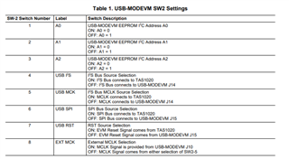
     - board connections ( like SW2 on USB MODEVM  and where we need to connect our DUT i2s pins and DAC output and ADC input and if any other       important connections related to clock and power ) for both Tx and Rx.

     - requesting separate code for ADC and DAC with MCLK-11.2896MHz(PLL on- since we are observing always this clock only), 32-bit width, BCLK-12.288MHz and sampling rate-192KHz.

    - we are trying both "usbmini-evm UI to flash codec config through i2c" and also our own i2c controller. please provide board connections for both.

    Regards

    Pavan

  • Hi Pavan,

    I had asked about what MCLK you were using so that I can give a working script. The MCLK is provided by your MCU, or in the case of the EVM, it can be provided by the TAS1020 which is a USB audio ASI chip on the EVM. If you are able to provide your own MCLK, then you can change the SW-2 switches to match your expected clocking. 

    If you want to get the EVM working with no external clocks, I would recommend you first try initializing the device with the GUI for the EVM - you can find that on the EVM product page or here: https://www.ti.com/tool/download/SLVC367

    There are example scripts in the application reference guide that expect an MCLK of 12.288MHz - which is the 48kHz sample rate version of your clock at 11.2896MHz. This allows for the PLL to be disabled and the dividers to give an OSR of 128. If you must use a script with no GUI on the EVM, you should choose one of the scripts in the reference guide that is written for 12.288MHz. It will work the same for you if your MCLK is 11.2896.

    Best,
    Mir

  • Hii Mir,


    Thanks for your resopnse

    In my case i am using the MCLK which is provided by EVM which is 11.896MHz. it can be provided by the TAS1020 which is a USB audio ASI chip on the EVM.

    I am requesing the following Requirements with - MCLK as 11.2896MHz from EVM.

    -PCM3070_Codec as Master mode
    -BCLK=12.288MHz,
    -Sampling rate=192KHz
    -Need separate code for the Codec Transmission(ADC) and Codec Reception(DAC)

    -In Codec Reception(RX) case:
    - Data coming from the SLAVE(DUT)


    In SW2 i am Keeping SW2_Pin 1,3 & 5 in ON and SW2_PIN 2,4,6,7,8 in OFF states for codec master mode. is it fine?

    Regards,

    Pavan

  • Hi Pavan,

    It will take me a day or two to write a script for you. You will need the PLL to multiply up the input clock to be sufficiently high enough to handle the internal clock requirements and OSR. I wonder can we adjust the EVM MCLK? Or, do you have an external clock for your end use case you can supply, of 12.288MHz? 11.2896MHz is a multiple of 44.1kHz, so maybe the EVM software has a 44.1kHz mode and a 48kHz mode. We would want the 48kHz mode for easier clock calculations, since 192kHz is a multiple of 48kHz as well. I do not have the EVM with me now but I can check tomorrow.

    Best,
    Mir

  • Hi Pavan,

    Were you able to change the sample rate to 48k on your computer so the MCLK provided on the board is 12.288MHz? We will not be able to generate the BCLK you want here with an MCLK of 11.2896MHz. If your end goal will provide a MCLK of 12.288MHz or some integer-related multiple of 48kHz, we can help with a script better.

    Best,
    Mir

  • Hi Mir,
    Thanks for your response.
    We are able to generate the required BCLK(12.288MHz) by using PLL. Attached code (Sending data from DUT to Codec (DAC)). We are using 32-bit and 192KHz sampling rate for DAC.
    Now we need generate same BCLK and 32-bit and 192KHz sampling rate for ADC code ( Sending data from Codec to DUT ). We will use same clock setting but we need your support in ADC registers configurations.

    Regards,

    Pavan

    w 30 00 00 # Initialize to Page 0
    w 30 01 01 # S/W Reset to initialize all registers
    w 30 04 43 # PLL enable
    w 30 05 91 # R & p values
    w 30 06 07 # J value
    w 30 07 18 # D values
    w 30 08 2f # D values
    w 30 0b 87# Power up the NDAC divider with value 7
    w 30 0c 82# Power up the MDAC divider with value 2
    w 30 0d 00# Program the OSR of DAC to 32
    w 30 0e 20# Program the OSR of DAC to 32
    
    w 30 1b 3c #i2s, 32 bits, bclk and wclk are OUTPUT from the device (master mode)
    
    # FOR MASTER MODE: dac_clk as input to bdiv_clkin, then n=2
    w 30 1d 00 
    w 30 1e 81 #BCLK ndiv = 1 to get 12.288MHz
    
    
    w 30 3c 08# Set the DAC Mode to PRB_P8
    
    # Select Page 1
    w 30 00 01
    
    w 30 01 08# Disable Internal Crude AVdd in presence of external AVdd supply or before powering up internal AVdd LDO
    w 30 02 00# Enable Master Analog Power Control
    w 30 7b 01# Set the REF charging time to 40ms
    w 30 0a 00# Set the input common mode to 0.9V
    
    w 30 14 25# HP soft stepping settings for optimal pop performance at power up
    w 30 0c 08# Route Left DAC to HPL
    w 30 0d 08# Route Right DAC to HPR
    w 30 03 00# Set the DAC PTM mode to PTM_P3/4
    w 30 04 00
    w 30 10 00# Set the HPL gain to 0dB
    w 30 11 00# Set the HPR gain to 0dB
    w 30 09 30# Power up HPL and HPR drivers
    
    
    # Select Page 0
    w 30 00 00
    
    # Power up the Left and Right DAC Channels with route the Left Audio digital data to
    # Left Channel DAC and Right Audio digital data to Right Channel DAC
    w 30 3f d6
    # Unmute the DAC digital volume control
    w 30 40 00

  • Hi Pavan,

    Mir is out of office so I will help briefly. I got this snippet from the application reference guide. Since the clock and power up steps are already present, this is just the ADC configurations:

    # Select ADC PTM_R4
    w 30 3d 00
    # Set MicPGA startup delay to 3.1ms
    w 30 47 32
    # Set the REF charging time to 40ms
    w 30 7b 01
    # Route IN1L to LEFT_P with 20K input impedance
    w 30 34 80
    # Route Common Mode to LEFT_M with impedance of 20K
    w 30 36 80
    # Route IN1R to RIGHT_P with input impedance of 20K
    w 30 37 80
    # Route Common Mode to RIGHT_M with impedance of 20K
    w 30 39 80
    # Unmute Left MICPGA, Gain selection of 6dB to make channel gain 0dB
    # Register of 6dB with input impedance of 20K => Channel Gain of 0dB
    w 30 3b 0c
    # Unmute Right MICPGA, Gain selection of 6dB to make channel gain 0dB
    # Register of 6dB with input impedance of 20K => Channel Gain of 0dB
    w 30 3c 0c
    # Select Page 0
    w 30 00 00
    # Power up Left and Right ADC Channels
    w 30 51 c0
    # Unmute Left and Right ADC Digital Volume Control.
    w 30 52 00

    Best regards,
    Jeff McPherson