This thread has been locked.

If you have a related question, please click the "Ask a related question" button in the top right corner. The newly created question will be automatically linked to this question.

TLV320AIC3104: ADC low level, high distortion in single ended mode

Part Number: TLV320AIC3104

Tool/software:

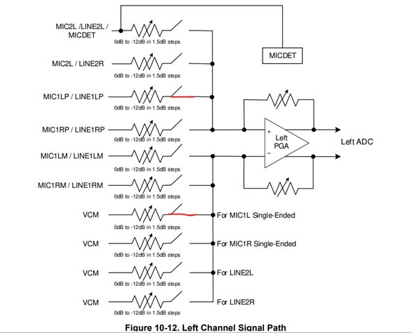
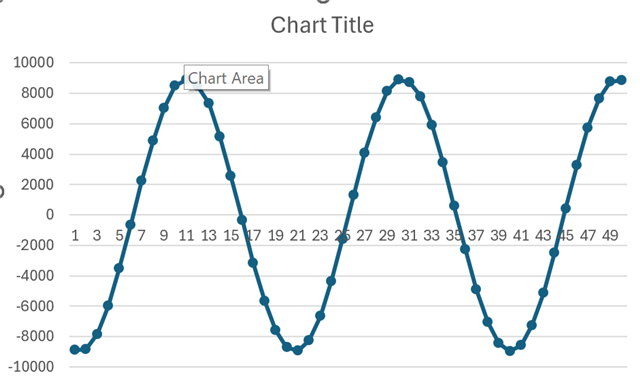
I am using the CODEC in single ended mode.  I set all the controls to 0dB and input a 2Vp-p sine wave on MIC1LP/LINE1LP.  If I look at the ADC output data, the signal never goes above 6000 or below -6000.  The waveform is distorted.  I have the MIC1LM connected directly to ground.  Does it need to be capacitively coupled to ground instead?  The datasheet has no singled ended example schematics.  This would be helpful.

Thanks,

Dave Gustavson

  • Hi David,

    1) When using single ended mode, the negative side of the PGA should be connected to VCM. It is recommended to AC couple MIC1LM to GND.

    2) Make sure to also double check that your I2S settings on the codec match what your receiver is expecting. That can often lead to scaling issues.

    Best regards,
    Jeff McPherson

  • Hi Jeff,

    Is hardwiring (no capacitor) MIC1LM to ground going to cause problems, either with that channel or also affecting the VCM for both channels?  I ask because the chip is very small and difficult to solder by hand.  My connection to ground is under the chip and will require unsoldering to cut the trace.  I don't want to do that unless I have to.  This is a mono application, and I have nothing connected to the right channel inputs.  I can try the capacitive coupling on that channel, but am I likely to get bad results because the grounding of MIC1LM will affect both channels?

    Thanks,

    Dave Gustavson

  • Hi David,

    The VCM connection is done internally via software. That is more important than grounding MIC1LM.

    However I don't recommend hardwiring MIC1LM to ground without a capacitor. There is an internal pullup on the input pins that will draw a lot of excess current if the input pin is connected directly to GND. Do you have any other ground available, even if it is not nearby to the chip? For this debug, the ground doesn't need to be very close.

    Best regards,
    Jeff McPherson

  • Hi Jeff,

    The issue with grounding MIC1LM is that it is underneath the chip.  I can't un-ground it without unsoldering the chip.

    What I could do was connect to MIC1RP and MIC1RM with tack wires.  This is the absolute limit of my soldering skills.  Capacitively coupling MIC1RM to ground yields this:

    The distortion is gone, but the amplitude is still low.  This is with a 2Vp-p sinewave input and register 21 set to 0 and register 15 set to 0.  This should be reaching +/- 32,000.

    If I look at the SPI data out, The MSb is not turning on.  Here is a scope screenshot with persistence turned up:

    Selecting the VCM connection you mentioned is done by bit D7=0 for Register 21, correct?  There is not a separate setting?

    Thanks,

    Dave Gustavson

  • Hi Dave,

    Yes, by setting bit 7 = 0 this will set the input to single ended mode. Register 19 is for MIC1LP/LINE1LP and Register 21 is for MIC1RP/LINE1RP.

    Best regards,
    Jeff McPherson

  • Hi Jeff,

    Any ideas about why the gain is so much lower than expected?  Is there a difference between using MIC2 vs MIC1 in single ended mode?  In the datasheet under ADC, it says the 0dB input level is 0.707Vrms in single ended mode.  Does that mean MIC2, since that input can only be single ended?

    Thanks,

    Dave Gustavson

  • Hi Dave,

    No there's no difference between Mic2 and Mic1. I imagine capacitively coupling the negative input to ground cleaned up the distortion and resolved some (but not all) of the scaling issues.

    There is also a 6dB gain difference between single ended and differential modes. If you applied a 0.707Vrms signal to MIC1P and left MIC1M ground, the ADC would ideally output -6dBFS even though you gave the full scale signal on the MIC1P pin because the ADC is expecting a signal on both input legs. Using single ended mode when only intending to provide a single ended signal ensures the scaling is correct. 

    Is that plot given with the device in single ended mode per Register 21? If it isn't then changing it should give you +-16000. There's an additional 6dB to find which might be related to your receiver settings. 6dB differences usually hint at some kind of bit shift mistake or something similar.

    Best regards,
    Jeff McPherson

  • Hi Jeff,

    I tried MIC2, and get the same signal level (+/-9000).  I understand your point about bit format the receiver is expecting.  That is why I posted the oscilloscope screen shot.  The yellow trace is the frame sync pulse, the blue is the pin 5, DOUT.  The MSb is never toggling, or there would be a faint persistence line on the blue trace that lines up with the falling edge of the pulse on the yellow trace.  The problem is definitely the data coming out of the TLV320AIC3104.

    Thanks,

    Dave Gustavson

  • Hi David,

    Agreed, the MSB not toggling is indicating the data out from the codec is at least partially responsible. Can you clarify for me if the Register 19 or 21 bit 7 is set to single ended mode? If you have a configuration script or a register dump of the codec when you're taking the measurements I can also look for any red flags in the config.

    Thanks,
    Jeff McPherson

  • Hi Jeff,

    My sincerest apologies for this wild goose chase.  Somewhere in all this try this, try that, I had set the AGC back on in register 26, at -12dB target.  It was working exactly as it is supposed to.

    Thanks,

    Dave Gustavson