Tool/software:
Hello,
we have the TAS5822MEVM and we are trying to configure and control it with a custom microcontroller.
The two audio amplifier on the boad are configured in "mono" (PBTL mode). The I2C bus from the microcontroller is connected in J19 and J18.
The I2S bus from the microcontroller is connected to the test points: SCLK, LRCLK and SDIN1, while jumpers of the headers J11, J13 and J14 are removed.
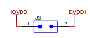
We are using the two header J3 and J7 to see which amplifier is being used, but in this situation we found that both header have 2.3 Volt on a pin 2 and 3.3V on pin 1, even if the jumper is not connected.
We would like to know why is the voltage on the header not zero on the pin 2 of J3 and J7. Is it suppose to be grounded when the jumper is disconnected?
Moreover, we would like to know the functions of the following:
S1
J12
and where is testpoint tp2?