This thread has been locked.

If you have a related question, please click the "Ask a related question" button in the top right corner. The newly created question will be automatically linked to this question.

TPA2015D1: What happens when balls are shorted.

Part Number: TPA2015D1

Tool/software:

Hi Team,

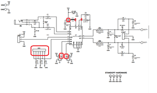
Currently, we are designing a PCB with TPA2015D1 on it
As our factory still uses old equipments, we cannot check if there are any balls shorted or not visually.
So we wanted to know what happens when there are shorted BGA balls.

Specifically, what happens if;
 1.PVOUT(A2) and SW(A3) are shorted.
 2.AGC(B3) and VBAT(B4) are shorted.
 3.SW(A3) and AGC(B3) are shorted.
 4.AGC(B3) and END(C3) are shorted.

Additionally, it's really helpful if anyone tells us what could happen when ENB or END is open.

P.S. The PCB we are designing is too dense to place test pads on it, so in-circuit test, too, is impossible.
 Which leaves us with only the function test to see if soldering went well or not.

Thank you in advance,
Hikaru

  • Hey Hikaru,

    These would have to be run and tested seeing as these are not events specified in the DS.

    Expect a response by next week.

    Regards,

    Ore.

  • Hi Ore,

    Thank you for your support. I really appreciate it.

    Best regards,
    Hikaru

  • No problem.

    Regards,

    Ore.

  • Hey Hikaru, 

    Here are my comments / observations:

    • This is equivalent to no input signal being inserted into the device. Shorting IN- and IN+ would simply allow the device output channels to be in an idle channel state. This is essentially putting the device in an "on but quiet" mode. 
    • If the output pin is shorted, the built-in over-current protection places the amp output in short circuit protection mode by deactivating the output signal

    For the remaining pins, although your requests are not specifically characterized by the DS and the results are not isolated to my setup alone, the device would behave abnormally if either of the following adjacent pins are shorted. You could get a different outcome or the following below:

    • short between the GAIN and AGC pins: no output signal 
    • short between END and ENB pins: distorted output signal 

    Please include in this thread the end equipment and customer.

    Regards,

    Ore.

  • Hi Ore,

    Thank you for the answer.
    Unfortunately, I don't really understand your answer.

    My questions were;
      Specifically, what happens if;
      1.PVOUT(A2) and SW(A3) are shorted.
      2.AGC(B3) and VBAT(B4) are shorted.
      3.SW(A3) and AGC(B3) are shorted.
      4.AGC(B3) and END(C3) are shorted.

    Since we connected GAIN to VBAT, we can say that no.2 was answered.
    But your answer doesn't cover other 3 questions, right?
    Am I missing something?

    By the way, I thought ENB and END can be conncted and controlled by an output port, like shown in Figure 7-15 and 7-16 of the DS.

    Best regards,
    Hikaru

  • Hey Hikaru, 

    You aren't missing anything. I was able to verify results mentioned on an EVM:

    case 1: I observed a normal output signal. I shorted L1 to C5 on the EVM

    case 2: I let this test run a little longer on different AGC modes and observed a non-distorted output signal that stabilized shortly. I shorted C5 to the different AGC modes. 

    case 3: I observed a normal output signal with different AGC modes as well. I shorted AGC modes to L1

    case 4: I observed a normal output signal here too. I shorted L1 to R6.

    For other cases:

    ENB and END work if there's a short between R5&R6. Let it run a little longer and the output is stable. 

    OUT+ AND OUT- short don't work and produce no output signal. Upon release, there's an auto recovered output signal.

    Open ENB and END pins by removing R5 and R6 show that the output signal is still produced.

    Although the amp still works in the short and open cases mentioned in this thread, these should be avoided during manufacturing as the long-term functionality of the device could be unpredictable as observed here.

    All cases were created upon power up and ran for approximately 2mins for the scope of this thread.

    Check out the EVM schematic and nodes probed/affected:

    Hikaru, was this able to answer your question?

    Regards,
    Ore.

  • Hi Ore,

    Thank you so much!
    Unfortunately, there is one question which isn't really answered.
     My question : 4.AGC(B3) and END(C3) are shorted.
     Your answer : case 4: I observed a normal output signal here too. I shorted L1 to R6.
    Shorting L1 and R6 is shorting A3 and C3, which aren't B3 and C3.
    But since B3 and C3 are both input terminal, I suppose I can safely imitate your way with our EVM.
    So, I will try it myself.
    Again thank you for your help.

    Best regards,
    Hikaru

  • Hey Hikaru, 

    These steps can be repeated on your end.  

    Shorting AGC and END provided an output as well. I shorted AGC jumpers to R6. 

    Regards,

    Ore