Tool/software:
Hi Ti,
Is there any problem with the following usage of LM4991?
Supply voltage: 5V
Maximum input signal amplitude: 5Vpp
Maximum output signal amplitude: 6Vpp (Av=1.2)
Best regards,
This thread has been locked.
If you have a related question, please click the "Ask a related question" button in the top right corner. The newly created question will be automatically linked to this question.
Tool/software:
Hi Ti,
Is there any problem with the following usage of LM4991?
Supply voltage: 5V
Maximum input signal amplitude: 5Vpp
Maximum output signal amplitude: 6Vpp (Av=1.2)
Best regards,
Hi Atsuo,
it seems this is not a good design.
the output level can't exceed the supply voltage, and in fact, usually it is a little lower than the supply voltage and there is loss inside the chipset.
and regarding the input signal, if it equals to the power supply, it may cause clipping.
Br,
Wenbin
Thank you for your prompt reply.
LM4991 is a bridge output, right?
In case of 6Vpp, I think the outputs of Vo1 and Vo2 are 3V, but is it different?
If so, I don't think the supply voltage is exceeded.
Best regards,
Hi Ti,
Sorry, I misunderstood.
My understanding is that Vo1 and Vo2 are outputs of 1V to 4V, respectively.
Therefore, I am aware that the supply voltage is not exceeded.
Best regards,
Hi Atsuo,
Yes, if the input signal is 5Vpeak to peak, it is ok.
and your design should be achieved.
Br,
Wenbin
Thank you for your prompt reply.
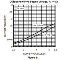
If 6Vpp is output into 8Ω load, the power will be 2.25W.
The datasheet states 1.5W (Typ.) when VDD=5V and RL=8Ω.
The graph also shows only up to 1.5W. (Figure 24)
Is there a problem?
Best regards,
Hi Atsuo,
in fact, 6Vpp is 3Vpeak and 2.12v rms. so the power is 2.12*2.12/8=0.56W.
regarding the 5V power @8Ohm load, it shows 1%THD is around 1.25W, it equals sqrt(1.25W*8Ohm)= 3.16V rms( 4.47 peak) or 8.94V peak to peak.

hope this helps for you to understand this figure.
Br,
Wenbin
Thank you for your careful explanation.
I now understand how to use it and that there is no problem.
Best regards,