This thread has been locked.

If you have a related question, please click the "Ask a related question" button in the top right corner. The newly created question will be automatically linked to this question.

TLV320AIC34: tdm configuration on am62x mcasp

Part Number: TLV320AIC34

Tool/software:

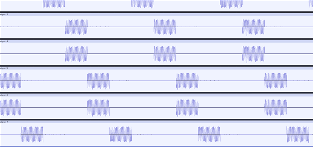
There are two codecs tlv320aic34 connected to mcasp1 on am62x, both A and B part of the codecs are being used, which means we have four codecs share the same cpu dai, they also share the same AXR0 for send and AXR1 for transmission. Pin LINE2LP LINE2LM LINE2RP LINE2RM are for line inputs and LEFT_LOP LEFT_LOM RIGHT_LOP RIGHT_LOM are for line outputs. I need to playback/record on the 4 codecs simultaneously.

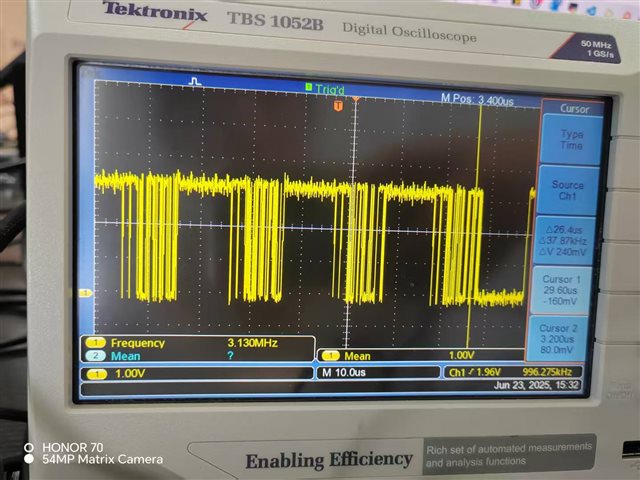
My question is do I have to create a new machine driver for this hardware configuration or simple-audio-card driver could apply? For me, I create a new machine driver with one cpu dai and four codecs, cpu is doing master, it has 8 slots and each 24 bit. data format is dsp_b. But I cannot hear any sound when playback. It seems working well from programming side with BCLK, FCLK and MCASPI outputting correct waveform. I set the LEFT and RIGHT DAX MUX to DAC_L3/R3 by amixer so that DAC is directly connected to LINEOUT. when I play the mute wav, the output on line out is a sine wave with relatively stable frequency of 1.18MHZ and amplitude. when I play other normal wav source, the output is a sine wave with continuously varying frequency and amplitude. The frequency is so high for human to hear. Please help how to figure out the problem.

The device tree is below:

&{/} {
sound {
compatible = "simple-audio-card-xxx";
simple-audio-card,name = "xxx";
#address-cells = <1>;
#size-cells = <0>;
simple-audio-card,widgets =
"Line", "codec1 Line In",
"Line", "codec1 Line Out",
"Line", "codec2 Line In",
"Line", "codec2 Line Out",
"Line", "codec3 Line In",
"Line", "codec3 Line Out",
"Line", "codec4 Line In",
"Line", "codec4 Line Out";
simple-audio-card,routing =
"codec1 LINE2L", "codec1 Line In",
"codec1 LINE2R", "codec1 Line In",
"codec1 Line Out", "codec1 LLOUT",
"codec1 Line Out", "codec1 RLOUT",
"codec2 LINE2L", "codec2 Line In",
"codec2 LINE2R", "codec2 Line In",
"codec2 Line Out", "codec2 LLOUT",
"codec2 Line Out", "codec2 RLOUT",
"codec3 LINE2L", "codec3 Line In",
"codec3 LINE2R", "codec3 Line In",
"codec3 Line Out", "codec3 LLOUT",
"codec3 Line Out", "codec3 RLOUT",
"codec4 LINE2L", "codec4 Line In",
"codec4 LINE2R", "codec4 Line In",
"codec4 Line Out", "codec4 LLOUT",
"codec4 Line Out", "codec4 RLOUT";
simple-audio-card,dai-link@0 {
reg = <0>;
format = "dsp_b";
bitclock-master = <&cpu>;
frame-master = <&cpu>;
bitclock-inversion;
cpu: cpu {
mclk-fs = <384>;
sound-dai = <&mcasp1>;
clocks = <&audio_refclk0>;
system-clock-direction-out;
dai-tdm-slot-num = <8>;
dai-tdm-slot-width = <24>;
dai-tdm-slot-tx-mask = <1 1 1 1 1 1 1 1>;
dai-tdm-slot-rx-mask = <1 1 1 1 1 1 1 1>;
};
codec_ports{
codec: codec@0 {
sound-dai = <&audio_codec1>;
dai-tdm-slot-num = <8>;
dai-tdm-slot-width = <24>;
dai-tdm-slot-tx-mask = <1 1 0 0 0 0 0 0>;
dai-tdm-slot-rx-mask = <1 1 0 0 0 0 0 0>;
};
codec1: codec@1 {
dai-tdm-slot-num = <8>;
dai-tdm-slot-width = <24>;
dai-tdm-slot-tx-mask = <0 0 1 1 0 0 0 0>;
dai-tdm-slot-rx-mask = <0 0 1 1 0 0 0 0>;
sound-dai = <&audio_codec2>;
};
codec2: codec@2 {
dai-tdm-slot-num = <8>;
dai-tdm-slot-width = <24>;
dai-tdm-slot-tx-mask = <0 0 0 0 1 1 0 0>;
dai-tdm-slot-rx-mask = <0 0 0 0 1 1 0 0>;
sound-dai = <&audio_codec3>;
};
codec3: codec@3 {
dai-tdm-slot-num = <8>;
dai-tdm-slot-width = <24>;
dai-tdm-slot-tx-mask = <0 0 0 0 0 0 1 1>;
dai-tdm-slot-rx-mask = <0 0 0 0 0 0 1 1>;
sound-dai = <&audio_codec4>;
};
};
};
};
};

  • Hi,

    Can you explain your issue more? You are able to get output but the frequency is too high? What files are you trying to play? Can you make sure that the files you are playing are at the appropriate sample rate? I see that your mclk-fs is 384, so your MCLK=384*samplerate, but what MCLK are you providing? I hope we can figure out your issue.

    Best,
    Mir

  • Yes, I could see the output on LINE OUT, but the frequency is too high, more than 1MHZ.  It seems the output is just some noise. I played a two-channel 440 Hz sine wave audio which is generated by audacity,sample rate is 44100. The Mclk is 384*44100=16934400HZ.  Is it normal that I play mute wav file, but the output  is a sine wave with relatively stable frequency of 1.18MHZ and amplitude? I could see all zero on DIN line when I play the mute file.

    I Try to simplify things a bit with using only one of the 4 codecs like 0x18 and let it to be the master and cpu to be the slave. The result is the same as that of tdm setting.

  • Hi,

    Any output from the DAC you see over 22kHz is going to be noise - maybe the 1.18MHz you are seeing is some factor of the internal modulator or something internal to the processor coupling into your scope lines. The DAC should have an output interpolation filter at 0.45*fs. Can you give me a register dump of the device to check the output and clocking settings? Are you providing BCLK and WCLK, or just MCLK? In your DTS file, it says your cpu is the master so it is generating BCLK and WCLK as well - are you able to measure those on a scope to check the frequency, making sure it is 44.1kHz on the WCLK and 8.4672MHz BCLK?

    Best,
    Mir

  • These are the registers of 0x0018# cat /sys/kernel/debug/regmap/1-0018/registers

    Addr | Value | Addr | Value | Addr | Value
    0x00 | 00 | 0x01 | 00 | 0x02 | 00
    0x03 | 18 | 0x04 | 04 | 0x05 | 00
    0x06 | 00 | 0x07 | 8A | 0x08 | 20
    0x09 | 60 | 0x0A | 60 | 0x0B | 01
    0x0C | 00 | 0x0D | 00 | 0x0E | 00
    0x0F | 50 | 0x10 | 50 | 0x11 | FF
    0x12 | FF | 0x13 | 00 | 0x14 | 80
    0x15 | 78 | 0x16 | 00 | 0x17 | 00
    0x18 | 78 | 0x19 | 00 | 0x1A | 00
    0x1B | FE | 0x1C | 00 | 0x1D | 00
    0x1E | FE | 0x1F | 00 | 0x20 | 18
    0x21 | 18 | 0x22 | 00 | 0x23 | 00
    0x24 | 00 | 0x25 | C0 | 0x26 | 00
    0x27 | 00 | 0x28 | 40 | 0x29 | 50
    0x2A | 00 | 0x2B | 2F | 0x2C | 2F
    0x2D | 2F | 0x2E | 2F | 0x2F | AF
    0x30 | 00 | 0x31 | 00 | 0x32 | 00
    0x33 | 9D | 0x34 | 2F | 0x35 | 2F
    0x36 | AF | 0x37 | 00 | 0x38 | 00
    0x39 | 00 | 0x3A | 0D | 0x3B | 00
    0x3C | 00 | 0x3D | 00 | 0x3E | 2F
    0x3F | 2F | 0x40 | AF | 0x41 | 9D
    0x42 | 00 | 0x43 | 00 | 0x44 | 00
    0x45 | 2F | 0x46 | 2F | 0x47 | AF
    0x48 | 0D | 0x49 | 2F | 0x4A | 2F
    0x4B | AF | 0x4C | 2F | 0x4D | 2F
    0x4E | AF | 0x4F | 09 | 0x50 | 2F
    0x51 | 2F | 0x52 | AF | 0x53 | 00
    0x54 | 00 | 0x55 | 00 | 0x56 | 99
    0x57 | 00 | 0x58 | 00 | 0x59 | 00
    0x5A | 2F | 0x5B | 2F | 0x5C | 2F
    0x5D | 99 | 0x5E | 00 | 0x5F | 00
    0x60 | 00 | 0x61 | 00 | 0x62 | 00
    0x63 | 00 | 0x64 | 00 | 0x65 | 01
    0x66 | 02 | 0x67 | 00 | 0x68 | 00
    0x69 | 00 | 0x6A | 00 | 0x6B | 00
    0x6C | 00 | 0x6D | 00 |

  •  FCLK   MCLK   BCLK   I find it is a little different from the exact value I set. I use the audio reference clock for mclk and the parent is <&k3_clks 157 7>;  Maybe I should use one of the codec as master. But I think it is not the reason that the output is noise.

  • Hi,

    Looks like your register 0x5e (register 94) is set to 00 so all outputs and L/R DAC are powered down - can you adjust your amixer settings to turn on the DAC and line outs to ensure that your issue is not this. Also, can you attach a schematic of your connections? What happens when you aplay a sine wave, and can you attach your reg dump during playback? 

    One more thing is that your clocks look like they are not providing a stable output level - and are around 3.3V, are you using a 3.3V IOVDD or 1.8V? The ASI clocks should be at the same level as IOVDD. I wonder if one of these problems is causing your output issue. 

    Best,
    Mir

  • register 94 is a read-only register. Its value should be set by register 37. It is a widget setting. You can see that 0x25 is set to 0xC0, which means LEFT DAC is on and RIGHT DAC is on too. I wonder why register 94  still shows DAC is not fully power off. l have already turned on the amixer settings related to DAC.

    The shematic shall kept private for NDA. What connections are you interested in, I could describe a little. the reg I dumped is already that I read during playback. 

    IOVDD is 3.3V  DVDD is 1.8V AVDD_DAC and DRVDD is 3.3V

    :dapm# amixer -c 0 get 'Line DAC'
    Simple mixer control 'Line DAC',0
    Capabilities: pvolume
    Playback channels: Front Left - Front Right
    Limits: Playback 0 - 118
    Mono:
    Front Left: Playback 118 [100%] [0.00dB]
    Front Right: Playback 118 [100%] [0.00dB]

    amixer -c 0 get 'Line'
    Simple mixer control 'Line',0
    Capabilities: pvolume pswitch
    Playback channels: Front Left - Front Right
    Limits: Playback 0 - 9
    Mono:
    Front Left: Playback 9 [100%] [9.00dB] [on]
    Front Right: Playback 9 [100%] [9.00dB] [on]

    amixer -c 0 get 'Left DAC Mux'
    Simple mixer control 'Left DAC Mux',0
    Capabilities: enum
    Items: 'DAC_L1' 'DAC_L3' 'DAC_L2'
    Item0: 'DAC_L3'

  • Hi,

    You can private message me directly with the schematic if you can. I would be interested in seeing what outputs you are using to measure on the scope and the ASI connections, as well as the power. 

    Best,
    Mir

  • okay, I sent you private message

  • Hi, playback is normal now. However  when I use arecord to capture a sine wave audio source, I capture all zero in my wav file. I mesure the input on LINE2L, it is a correct sine wave  with zero DC offset, oscillating symmetrically around 0V. I could see the signal change on mcasp rx line, but the voltage is not very correct, it should be 3.3V but actually it is 2.6V. Below are the codec register I dump during the capture process.

    arecord -D hw:0,0 -f S16_LE -c 8 -r 48000 output.wav

    Register 36 is all zero, but I have already set register 22 and register 19 to power on ADC

    Address Value  Address Value  Address Value 
    0 0 1 0 2 0
    3 94 4 10 5 0
    6 0 7 0a 8 20
    9 78 0a 0 0b 1
    0c 0 0d 0 0e 0
    0f 77 10 77 11 ff
    12 ff 13 4 14 80
    15 78 16 4 17 80
    18 78 19 0 1a 0
    1b fe 1c 0 1d 0
    1e fe 1f 0 20 18
    21 18 22 0 23 0
    24 0 25 0 26 0
    27 0 28 40 29 50
    2a 0 2b 80 2c 80
    2d 2f 2e 2f 2f af
    30 0 31 0 32 0
    33 9c 34 2f 35 2f
    36 af 37 0 38 0
    39 0 3a 0c 3b 0
    3c 0 3d 0 3e 2f
    3f 2f 40 af 41 9c
    42 0 43 0 44 0
    45 2f 46 2f 47 af
    48 0c 49 2f 4a 2f
    4b af 4c 2f 4d 2f
    4e af 4f 8 50 2f
    51 2f 52 af 53 0
    54 0 55 0 56 98
    57 0 58 0 59 0
    5a 2f 5b 2f 5c af
    5d 98 5e 0 5f 0
    60 0 61 0 62 0
    63 0 64 0 65 0
    66 2 67 0 68 0
    69 0 6a 0 6b 0
    6c 0 6d 0
  • Hi,

    Can you share the scope capture of the rx line showing the lower voltage?

    Thanks,
    Jeff McPherson

  • Considering the mclk we output too high(100MHZ),  I change it to 20MHZ, then the output voltage on rx line is 3.3V normally. But the problem is the audio file I record is still all zero.

    And Since the cpu output bitclk is not very precise,  I use one of the codecs as clock master and provide bitclk and fclk.The rxline output is what as below.

  • Hi,

    Looking through your most recent register settings, it looks mostly normal - are you able to read the registers back from the AIC34? I think there are some read-only registers that are not what I would expect, so is the register setting you sent what you set but not read back? What command are you using to dump the I2C? Another thing is that micbias is powered down, do you need your inputs biased to enable the microphone? If you are able to read the i2c itself, the commands should be fine. Can you tell me what your MCLK and BCLK you expect are?

    Best,
    Mir

  • I read through regmap driver, but it is cached values. I disable the cache and got some new registers value as below. I do not need microphone now. I use Line2L&R as audio analog inputs, which you could see on the schematic.  the MCLK is 20MHZ, and BCLK is now fixed 256*FCLK, since the codec tlv320aic34 is used as clk master now and could only provide 256-tdm mode. Are there any problems with the rx lineout signals refering to the scope capture I posted before?
    0x00: 0x00
    0x01: 0x00
    0x02: 0x00
    0x03: 0x91
    0x04: 0x10
    0x05: 0x8F
    0x06: 0x00
    0x07: 0x0A
    0x08: 0xE0
    0x09: 0x48
    0x0A: 0x60
    0x0B: 0x01
    0x0C: 0x00
    0x0D: 0x00
    0x0E: 0x00
    0x0F: 0x77
    0x10: 0x77
    0x11: 0xFF
    0x12: 0xFF
    0x13: 0x7C
    0x14: 0x80
    0x15: 0xF8
    0x16: 0xFC
    0x17: 0x80
    0x18: 0xF8
    0x19: 0x06
    0x1A: 0x00
    0x1B: 0xFE
    0x1C: 0x00
    0x1D: 0x00
    0x1E: 0xFE
    0x1F: 0x00
    0x20: 0x00
    0x21: 0x00
    0x22: 0x00
    0x23: 0x00
    0x24: 0xCC
    0x25: 0x00
    0x26: 0x00
    0x27: 0x00
    0x28: 0x40
    0x29: 0x50
    0x2A: 0x00
    0x2B: 0x80
    0x2C: 0x80
    0x2D: 0x2F
    0x2E: 0x2F
    0x2F: 0xAF
    0x30: 0x00
    0x31: 0x00
    0x32: 0x00
    0x33: 0x9C
    0x34: 0x2F
    0x35: 0x2F
    0x36: 0xAF
    0x37: 0x00
    0x38: 0x00
    0x39: 0x00
    0x3A: 0x0C
    0x3B: 0x00
    0x3C: 0x00
    0x3D: 0x00
    0x3E: 0x2F
    0x3F: 0x2F
    0x40: 0xAF
    0x41: 0x9C
    0x42: 0x00
    0x43: 0x00
    0x44: 0x00
    0x45: 0x2F
    0x46: 0x2F
    0x47: 0xAF
    0x48: 0x0C
    0x49: 0x2F
    0x4A: 0x2F
    0x4B: 0xAF
    0x4C: 0x2F
    0x4D: 0x2F
    0x4E: 0xAF
    0x4F: 0x08
    0x50: 0x76
    0x51: 0x76
    0x52: 0x00
    0x53: 0x00
    0x54: 0x00
    0x55: 0x00
    0x56: 0x98
    0x57: 0x00
    0x58: 0x00
    0x59: 0x00
    0x5A: 0x76
    0x5B: 0x76
    0x5C: 0x00
    0x5D: 0x98
    0x5E: 0x00
    0x5F: 0x00
    0x60: 0x00
    0x61: 0x00
    0x62: 0x00
    0x63: 0x00
    0x64: 0x00
    0x65: 0xC0
    0x66: 0x02
    0x67: 0x00
    0x68: 0x00
    0x69: 0x00
    0x6A: 0x00
    0x6B: 0x00
    0x6C: 0x00
    0x6D: 0x00

  • Hi,

    I will look through your registers tomorrow, sorry about the delay. The I2C looked maybe fine, it looks like it may be inverted with such long stretches of high signal compared to your previous scope shot of low voltage?

    Are you providing MCLK and BCLK or just MCLK? Why do you need 256 TDM mode? 

    Best,
    Mir

  • cpu provide MCLK, codec provide BCLK and MCLK.  Because for TDM mode, I think codec only supports 256TDM mode.

  • in continuous transfer mode, number of bit clocks per frame is two times the data width, but I need 8 slots per frame.

  • I swap the AXR0 and AXR1 line, which means AXR0 to be used as the codec rx and AXR1 to be used as codec tx, then I am able to record the audio data. The playback is also normal. I am confused.

    There is another thing confusing, When there are only channel 1 and channel 2 having audio signal input, if I record 8 channels, then the audio data recorded is evenly distributed across 8 channels(I attach the screenshot on audacity tool). If I record only 2 channels, the saved data is normal. How should I modify this to let data only appear on the first two channels? attached is the recorded audio data for 8 and 2 channels.

  • Hi,

    If you switch to regular I2S mode instead of 256-TDM, that should help with only outputting stereo. You should still be able to use a 256*WCLK as your BCLK, just there will be some cycles unused. Do you mean to be inputting 8 channels of TDM and only output on the first two? If so, I can look more into the reg map and help you out there, tomorrow.

    Best,
    Mir

  • I have configured 8 TDM channels in the device tree. During my test, only the first two physical Line2 IN inputs actually have analog audio signals connected. The remaining 6 channels have no valid analog input.

    When I run the following recording commands:

    arecord -D hw:0,0 -f S32_LE -c 2 -r 48000 output.wav

    The recorded data is correct for both channels.

    But when I run:

    arecord -D hw:0,0 -f S32_LE -c 8 -r 48000 output.wav

    The recorded data is not as expected.
    I expect:

    • The first two channels to contain valid audio data

    • The remaining six channels to be filled with zeros

    But in reality:

    • All 8 channels contain data, and the invalid channels seem to have duplicated or unexpected content

    • It appears that the valid data from the first two channels gets redistributed or repeated across the 8 output channels

    I would like to know:
     White check mark How can I ensure the invalid channels are filled with zeros as expected?
     White check mark Is this caused by ALSA behavior, driver configuration, or hardware settings?

  • Hi,

    I am trying to run your configuration on my EVM to get a better idea of how this is happening, but am not getting a stable output WCLK/BCLK. Are you able to measure your clocks and data when you record with 2 vs 8 channels so we can see the difference? I wonder if you are having issues when you change the number of channels with ALSA, does ALSA know that your BCLK is constant? Let's see if you are getting audio data during the clock cycles that are unused.

    Please send over some scope shots if you can so we can further debug. Another question - why is your offset=96 BCLKs in register 0x0a (10d)?

    Best,
    Mir

  • After I add -period-size=8 parameter to arecord -D hw:0,0 -f S16_LE -c 8 -r 48000 -d 10 output.wav --period-size=8, I could solve the problem that audio data of 2 channels being distributed to other 6 channels.

    I have measured the clocks and data when I record with 2 vs 8 channels, there is no difference. I think the driver do the things that mask invalid data in the slot and then send the data to alsa.

    I also found the root cause that make me unable to record audio before. It is the pin mux, I set the RX pin of mcasp as output in devicetree.  But I do not know why the output setting causes the mcasp controller unable to get the data.

    When I used the cpu as master, I also changed the audio refrence clock's parent so that it use the same parent as mcasp IO's.

    I tried to set different slot size during debug, so when the offset is 96, I think the slot size if maybe 24/16.

  • Hi,

    Glad you got it figured out. Do you need more help or did you figure out how to solve your problems here?

    -Mir