Tool/software:
Hello.
I attached the new op amp schematic opm320-v1_06-12pcs-2024119-circuit.pdf schematic to you before, and here is the explanation of some changes.
- Some changes have been made.
- it is produced with this final change so far.
The new opamp schematic opm320-v1_06-12pcs-2024119-circuit.pdf schematic had final changes as we produced it.
The reasons for the changes are as follows:
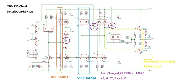
1-1. To reduce the power quiescent current, we increased R7 from 75R0 to 100R0 to reduce the reference current.
As a result, the power standby current is about 7mA~12mA in total.
1-2. c3 and c6 were removed from 27pF to 0pF to increase the rolloff frequency of the high frequency band.
That's all the changes. In this state, 1 channel is produced by soldering individual parts to a small PCB, and the single-type product is produced by placing one circuit, and the dual-type product is produced by placing two circuits.
continue.
The attached circuit diagram OPM320 Circuit Description-Rev1.3.pdf is also shown and explained.7215.OPM320 Circuit Description-Rev1.18-ENG-c3-v1.6.pdf