A related question is a question created from another question. When the related question is created, it will be automatically linked to the original question.
If you have a related question, please click the "Ask a related question" button in the top right corner. The newly created question will be automatically linked to this question.
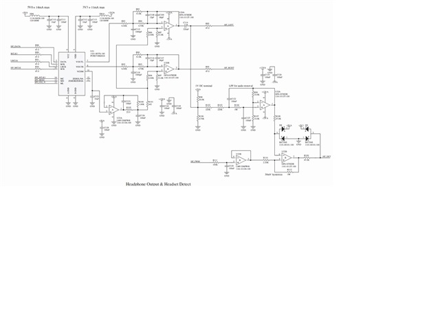
Could you help to check the PC1748 mute function by external control circuits. We would like to have the PCM1748 hardware mute while AC on or DC on. That may prevent the POP sound issue on headset when AC on, thanks.
Currently, PCM1748 PIN11/12 are NC now.
The pins can be used to operate external mute circuits.
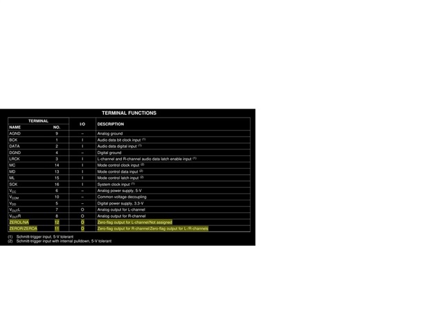
And the PINs(PIN12:zeroL/ PIN11:zeroR) function is output only, how to do the external mute circuits for PCM1748 application circuits.
Thanks for waiting as I was out of office. The PIN12:zeroL/ PIN11:zeroR are output pins so they can be used as flag signals that can be connected to the circuit that is connected to the output of the DAC. For example, the output of the DAC is going to an amplifier stage ( for adjusting gain or low pass filtering or ...) So this signal can be connected to the MUTE pin of the amplifier to mute it once a zero signal is detected on any or both of these pins.
This device has internal soft mute that is controlled by registers , so may be can check the possibility of using the ZERO flag in the system to trigger a request the soft mute activation.
So, the bottom line is that pin 11 and 12 are output pin and can not be used as inputs to accept a signal.