This thread has been locked.

If you have a related question, please click the "Ask a related question" button in the top right corner. The newly created question will be automatically linked to this question.

PCM5102A: Incorrect oversampling rate

Part Number: PCM5102A
Other Parts Discussed in Thread: PGA2311, PCM5102

Tool/software:

Hello,

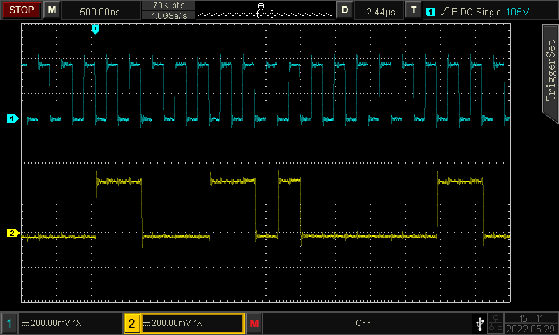
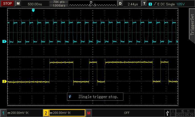
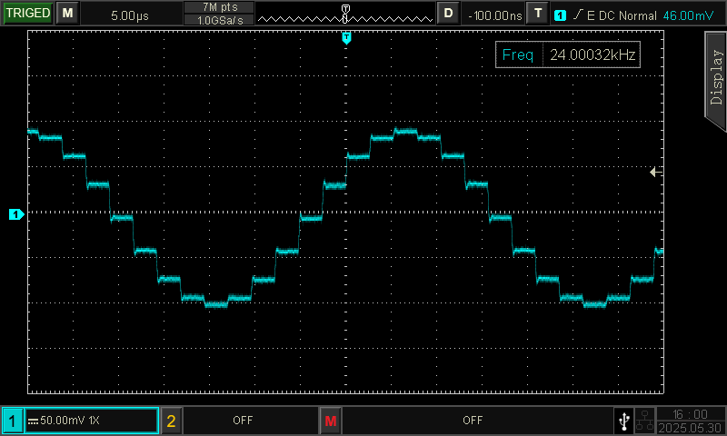
After using two PCM5102A in an audio application for several months working fine both IC changed behaviour concerning oversampling rate. There is no changing in hard- or software after running the application first, all digital signals and all supply voltages are OK. I attach a screenshot of the DAC output signal.

Conditions are: SCK 12.288 MHz, BCK 3.072 MHz (32 bit per channel), LRCK 48 kHz, sine wave of 24 kHz

Without oversampling there should be two square wave pulses per period, one with a positive and one with a negative amplitude. The number of steps here is 16, so it is 8 times oversampling instead of 256. I tested with SCK input grounded, no difference. Digital signals are generated from SPDIF receiver WM8804, left justified PCM, output of DAC is loaded with RC filter (680R + 2.2nF) and the input of a PGA2311 (Rin 10k).

I can exclude an ESD damage. After detecting this error I populated another board, with two new DAC from the same delivery as the both used ones. The oversampling rate is also not correct.

Hope you have an idea where I should pay attention to.

  • Hello,

    This is a simple device that has no registers to configure so if there is no change in the hardware (internal  filter configuration , input format and etc )  then it has to be the incoming signals to the device. The clock rates you mentioned are all correct to me, just make sure what you think  is going to the device,  is indeed confirmed.

    This is a segmented DAC and  from your plot, it seems only MSB section is working and may be there is  no LSB data available to it  to be processed . So please make sure the input data is verified.

    Also I do not believe there is any issue with the device itself, including ESD damage or other device related issue.

    I would start from a simple 1KHz input sinewave and monitor the format of Din by probing Din, LRCLK and BCK in the same plot/screen,   so you can verify the edges and thus its format. Also I would use the SCK since without it (if  SCK is connected to GND) the PLL will be activated and this  brings other parameters into the picture. 

    Try to experiment  with different SCK rates as well but make sure you stay within the spec of Table 10.

    If problem still exists, send me screenshots of the above signals in the same window, as well as output before getting to PGA2311.

    Regards,

    Arash

  • Hello Arash,

    Thanks for reply.

    During my troubleshooting I changed also level of digital input signal, output signal of DAC looked the same, just smaller. Circuit is running only with 44.1kHz and 48kHz sample rate, I checked both, problem is the same.
    Sine wave signal levels with data only in the MSB region are valid audio levels and there should be no noticable steps visible with 256 fs oversampling. It should be a sine wave with HF noise at the DAC output and suppressed HF noise behind the RC filter.

    I will check all digital input signals and come back to you with screenshots. I also received same new PCM5102A today.

    Best regards
    Wolfgang

  • Thanks, let me know how it goes.

    Regards,

    Arash

  • Hello Arash,

    attached you can find screenshots of the input port. Triggering is caused from rising edge of LR signal, you can see bitclock and data written into the DAC. Hardware setting of PCM5102A is for left justified audio data transmission. Can you see something wrong here? I can't.

    Replacing of IC doesn't help either, behaviour is unchanged.

    There is a previous version of this hardware module, some hardware circuit and software but with a WM8524 DAC. I changed the DAC to have advantage of the lower noise level of PCM5102A, and I could measure the difference. The electronic module using WM8524 is still working with 256 times oversampling and I wonder what happened to PCM5102A.

    Best regards,

    Wolfgang

    PS.: It is not possible for me to insert the screenshots here. The <Insert> image of this editor seems not  working.

  • Hello Wolfgang,

    I didn't suspect the IC itself was the issue and by swapping it you confirmed it. WM8524 and PCM5102 are also similar in functionality so  still I think the issue is the I2S format or clks. May be if you can manage to send the screenshots, it  can help me review them to confirm your observation. The other option is to use the EVM for PCM5102 or any other proven EVM with a DAC on it and send the same (EXACT) I2S to that and see if there is still the issue exists.

    Regards,

    Arash

  • Dear Arash,

    I'm using left justified data format. I could upload the screenshots!

    Explanations to signals in my last message. If you need more/different signal recording for clarification please let me know. 

    Best regards

    Wolfgang

  • Hello  Wolfgang,

    Would you please include the complete cycle of R and L channel (  Din, LRCLK and BCK,   similar to Figure 13 in datasheet -since  without LRCLK waveform nothing is meaningful)  

    Also please send me the schematic of your board. It would be useful if you send  the old version of your design that was working for you. 

    Have you tried different SCK & grounding SCK to get more data point to debug? please  confirm VNEG and LDO voltages are fine ( they should be, but check them again) 

    Once you have collected the needed data, if I don't see any issue  with the input signals or design -  you  may want to send your board to me and I can try to debug it here or you can   acquire  a  different board ( preferably the PCM5102 EVM  ) and test it with your I2S signals, so we can pin point the issue.

    Regards,

    Arash 

  • Hello Arash,

    let me summarize what I did before contacting TI:
    I checked all supply voltages (including LDO and VNEG), they are constant, no oscillation , no failures and inside the allowed ranges.
    I checked the digital signals, all four data inputs are according the data sheet requirements. (BCK and SCK were checked for temporary failures or jitter with the persistent mode of the digital scope)
    I checked the soldering joints without finding bad contacts.

    SPDIF signal generating is accomplished with a PC software and a USB sound module. At a sampling rate of 48kHz and a signal frequency of 24kHz it generates the minimum and maximum peak value of the sine wave (e.g. +32767 and -32767 or smaller), only two samples per period of the sine wave!
    The two screenshots I send to you in the last message are comparable to figure 13 of the PCM5102A data sheet, they show these two values. A negative value (~data1.bmp, first and most significant bit is high) and the positve one (~data2.bmp, first and most significant bit is low). Trigger point is marked with a T and corresponds to the rising edge of the LRCLK. BCK is 3.072MHz, data is output at the falling edge of BCK and valid with the rising edge of BCK (take over the value). Because LRCLK is high the data will be output on the left channel of the DAC.
     
    In this hardware I can only work with 44,1 and 48kHz sampling frequency, I checked both, with SCK applied and without SCK applied (SCK = 0). The problem is always the same, the oversampling factor is wrong. The only reason I can imagine for this behaviour is a wrong BCK or SCK, but in my opinion these signals are OK.

    Please provide me with an explanation about the date code marked on top of the IC. Is it possible to get a sample of PCM5102A that is produced recently? I would like to try out another sample first, maybe it is a matter of age. For the screenshots you asked for I need to have access to a four channel scope. If you think this would be necessary for evaluation I will submit some later.

    Best regards,

    Wolfgang

  • Hello  Wolfgang,

    Thanks for the overview, I don't think this is matter of age of the IC, moreover  you have replaced the IC before, so it is not the chip issue nor the lot issue.

    If you want to check date code, the first 2 digits after the BB logo  is the YM (year and month).   Probably if we order something, it is from the most recent lots, but that I can not tell for sure. This part was originally  released in 2012 

    If you have verified the I2s  as it compares to  figure 13 , I don't think it will be much help to reverify it at my end again.

    My  suggestion is to do the test  I mentioned before: Try the  exact I2S that is coming into this board , with another board which has been working with no issue. If it works on the other board, then  we can suspect something is wrong with this IC (as you have already verified all signals and supplies including VNEG and LDO this chip and this is HW control and the board is simple ). The best option is to try PCM5102A EVM itself, because you have the option of replacing its IC with yours to confirm the IC has no issue. Let me see if we can send you few samples.

    Please give me your shipping address  as well as email  while I am checking this for you.

    If you want you can send me your board and  I am willing to debug it here for you. Let me know if I can be of any assistance.

    Regards,

    Arash

  • Hello Arash,

    thanks for your offer to debug the circuit on your site. If I can't find the reason for the malfunction I will come back to you.

    My PCM5102A samples have a date code of 31 and 39. If TI has samples in stock that are much younger than mine I would like to try again with one new IC. At this time I don't have any board with working PCM5102A. The older version of this board contain the DACs WM8524 from Wolfson/Cirrus, still working fine concerning oversampling factor. Because of different pinning it is not possible to use PCM5102A on this boards. Just to mention it again: the board with the PCM5102A was working fine for about 9 months, than the problem with the oversampling rate comes up. There were no changes in hardware or software during this time, the circuit is a digital crossover to build active loudspeaker systems. 

    If you can clarify the production date of the TI samples, I would like to order samples with the help of my TI account. (Is this conversation public? I'm not sure about that.)

    Thank you again, best regards,

    Wolfgang

  • Hello  Wolfgang,

    Yes, This is a public forum so conversation is not private. You can click on my name and then connect and send me your information.

    From your original description I didn't read it as the board was working for few months. So if the same board was working fine for 9 months with the same inputs from the same source, it means an IC is not working correctly now and of course the main suspect is the DAC. However  I find it extremely strange that when swapping the DAC, the problem persist. Because if there was a lot issue and  for some reason it scaped from the tester , we would  have heard  from many different users.

    If you want, just send me one of the DACs, and I will test it at my end and if there is an issue I can send it to Failure Analysis team to pin point the problem, or I can send you free samples to test them on your board- but I have no way to know about the time code on the new samples. I think  the best and fastest solution is that I send you some  samples so you don't lose time and we go from there.

    Regards,

    Arash

  • Hello Arash,

    OK, I have three new samples left with date code 39, I can send them to you. I will send my contact information separately.

    Best regards,

    Wolfgang

  • Thanks Wolfgang. 

    I sent you instructions and address. Regards,

    Arash

  • Closing this as new samples are ordered.

    Regards,

    Arash

  • Hello Arash,

    I prepared a test circuit for PCM5102A to check with different sample rates of 32kHz and 96kHz, the problem persists. Please find attached the schematic. I add also a screenshot of a signal with 256 times oversampling, the sine wave is the output signal of WM8524 under same conditions as PCM5102A. Please compare the signal with the first screenshot at the beginning of this chat.

    Best regards

    Wolfgang

    TestCircuit.pdf

  • Hello, 

    I assume the waveform above ( which is what we expect to get)  is from WM8524 on a different board ( may be similar or even identical layout ) but not the same board that PCM5102A is sitting on it at the moment . So that leaves  the possibility of issue with other components  on the board, not necessarily the DAC itself, and the new samples could confirm that.

    If the new samples work fine on the same old board that was working for a while,  then it confirms it is the DAC's issue ,and if they still  fail on your board, then you should check other components on the board.

    I will be out of office until next Wednesday, may be by that time you can let me know if new samples fix the issue.

    Regards,

    Arash