This thread has been locked.

If you have a related question, please click the "Ask a related question" button in the top right corner. The newly created question will be automatically linked to this question.

OPA1622: Multiplexing OPA1622 outputs

Part Number: OPA1622
Other Parts Discussed in Thread: INA1620, , OPA1637

Tool/software:

So, as is the way of engineers, I have seen a square hole and a round peg, and decided the two must meet.

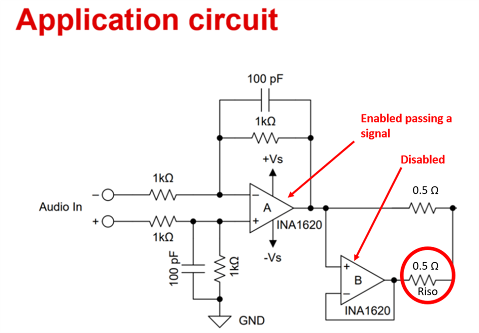
I have an application where I need to be able to toggle between multiple amplifiers with different gain configurations rapidly, without using mechanical relays, and without measurable degradation of the distortion or noise performance when loaded between 4 and 600Ω. I also need to achieve a total output noise below 1uVrms for 22khz bandwidth, and distortion products below that with 2Vrms out. Easy ask, right? The OPA1622/INA1620 seemed like a lifeline here, until I got to this page in the datasheet

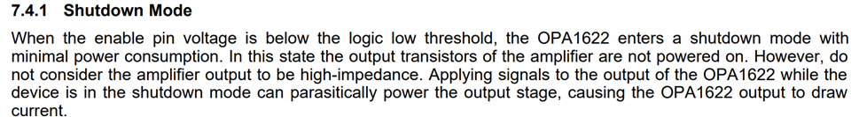
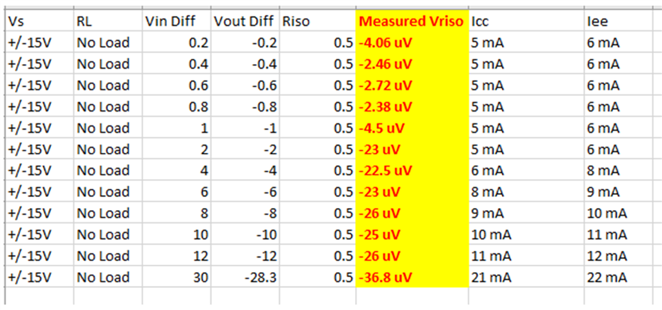
Now, if I literally do exactly the opposite of what I'm being told to here and *did* put, say, 4 OPA1622s with their outputs and inputs in parallel, and selectively used the EN pin to activate them one at a time, what's the impact of the parasitically powered output stages assuming that each of the 1622s has negligible output impedance beyond its own Zout? My intuition would be that, while not high-Z, the source impedance of the parasitic components would be significant enough to make their contribution at the output quite small, but my intuition is also that my wrench is a good hammer, so I'm asking here.

Alternatively, are there any ultra-low-noise, ultra-low-distortion opamps that do support shutdown with the output in high-Z state? I've found the OPA1637, but I need a difference amplifier, not an FDA.

  • Hi Blaine, 

    By the way the INA1620 is the OPA1622 but with integrated resistors. While the output stage shouldn't be considered High Z, it also isn't low z either. I have successfully paralleled two INA160's/OPA1622's together exactly as shown in the app note here with no issue for headphone drivers. I even tested down to around 1 ohm load.

    For the shutdown test I chose a no load to ensure I measured with the maximum output swing in an attempt to turn on the output stage. I toggled the amp on and off while passing signals to see if I can break it. The column in yellow is the measured voltage across the 0.5 ohm resistor. There are two INA1620 devices used. Two amps are the main drivers where the other INA1620 parallels the first two. The second chip is the one getting toggled on and off. This is for left and right channels on a headphone. You can see that worst case I am getting 36.8uV/0.5ohms = 73.6uA. To confirm my results I also had the designer run simulations and he confirmed my results in his sims. 

    I hope you find this information useful. 

    Best Regards, 

    Chris Featherstone

  • Hi Chris, thank you very much for the reply. The measurement is appreciated, although I'm actually more concerned with the behavior at the output node (that is, the signal going into the headphones) - my goal with the design is to avoid distortion exceeding -125dB relative to the signal with the output loaded within the linear range of the 1622/1620. 

    It's very good to know that it won't break the 1622/1620 to have the outputs in parallel (through small isolation resistors) and selectively enable, though - with that I can probably justify just running a test board for this and getting my own answers rather than bugging you.

  • Hey Blaine, 

    Anytime. If you have any interesting results let us know. Let me know if I can be of further assistance. 

    Best Regards, 
    Chris Featherstone