This thread has been locked.

If you have a related question, please click the "Ask a related question" button in the top right corner. The newly created question will be automatically linked to this question.

PCM5102A: Relationship between LRCK, BCK, and SCK frequencies

Part Number: PCM5102A

Tool/software:

質問させてください。
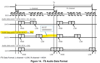
PCM5102Aにてサンプリングレート256kHzを実現しようとしています。FPGAよりLRCK, BCK, and SCK を入力する構成で考えています。各クロックの周波数はLRCK:256kHzBCK:16.384MHz (fs×64)SCK:16.384MHzでも動作しますでしょうか。SCKに関しての関係性の制約がデータシートには記載されていないので問題ないと考えています。(PCM5102Aはスレーブ動作で通信フォーマットはI2Sです。)

%MCEペーストビン%

  • Hello, 

     For some reason I can not translate it in English using Google. So based on your title I am answering your question. the relationship b/w BCLK and LRCK is given by 

    BCLK= # of Ch.  *  Ch depth  * Fs and once you have your LRCLK selected the relationship with SCK is given by the Table 10. System Master Clock Inputs for Audio Related Clocks

    Let me know if this is not your question.

    Thanks

    Arash

  • I apologise for posting in Japanese. I will write in English.

    I am trying to achieve a sampling rate of 256 KHz with PCM5102A.(The data width is 24 bits.)

    I am considering a configuration in which LRCK, BCK, and SCK are input from the FPGA.

    Would the following clock frequencies work: LRCK: 256 kHz, BCK: 16.384 MHz (fs × 64), and SCK: 16.384 MHz?

    Since there are no constraints regarding the relationship between SCK and the data sheet, I believe there should be no issues.

    (The PCM5102A operates in slave mode with an I2S communication format.)

    Table 10 does not list a sampling frequency of 256 kHz. Is 64 fs acceptable for fsck?

  • Hello, 

    The part accepts fs of 8K to 384KHz, so 256KHz is ok but using the above equation and (The data width is 24 bits.)

    BCK=2x24x256k=12.229MHz,  So for BCK of 16.384MHz, it has to be 32b wide.

    Table 10 is for  common audio rate and thus 256 kHz is not  in the table . 

    Even though we don't have any official  information for fs=256K in the table , I believe  if you use 32Bit data with BCK=SCK=16.384 MHz in software mode it should work .

    Kind Regards,

    arash

  • 図 14 を見ると、BCK は 24 ビット幅の場合、48fs と 64fs の両方をサポートしているように見えます。
    この場合、24fsで64ビットBCKを使用することを検討しています。その場合、LSB(24ビット)の残りのデータは0にすべきでしょうか。

    SCKもBCKと同じ16.384MHzで問題ないことを確認していただきありがとうございます。

  • Hello, would you please post your questions in English.

    Thanks,

    Arash

  • I apologise for not using English.
    Looking at Figure 14, it appears that BCK supports both 48fs and 64fs when the width is 24 bits.
    In this case, we are considering using 64fs BCK with a width of 24 bits. In that case, should the data after the LSB (24 bits) be set to 0?

    Thank you for confirming that SCK is also 16.384MHz, the same as BCK, and that there are no problems.

  • Hello Shota,

    Yes,  you need to  fill with zeros to get to 32bit for the given clks per equation.

    Although TI  does  not officially have any data for the noncommon audio fs of 256KHz in the datasheet, I personally think it should be ok. Keep in mind,  SCK rates that are not common to standard audio clocks, between 1 MHz and 50 MHz, are only supported in software mode

    Regards,

    Arash

  • In this case, I understand that there is no problem with the usage described in the first question, which is to input LRCK: 256 kHz, SCK: 16.384 MHz, BCK: 16.384 MHz, and DATA from the FPGA to the PCM5102A.

  • Yes sir. I believe it should work fine. 

    Regards,

    Arash