TAA5242: MD2:1 setting and gain value

Part Number: TAA5242

Tool/software:

Hi,

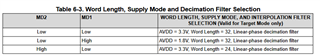
1. When operating at Fs=192 kHz with the following settings, the gain is +6dB. When operating at Fs=48 kHz or 96 kHz by changing the CCLK, the gain is also +6dB.

    I could not find the specification of gain +6dB on the data sheet, but is this correct operation?

2. As shown in the attached measurement results, the output level differs between Single-end and Single-end w/high common mode. Is it the specification of this IC that the output changes depending on the pin setting regardless of the input level?

TAA5242 MDx setting and Input_Output level - コピー.xlsx


< Setting >
The following settings are made in the Controller mode of the ADC.
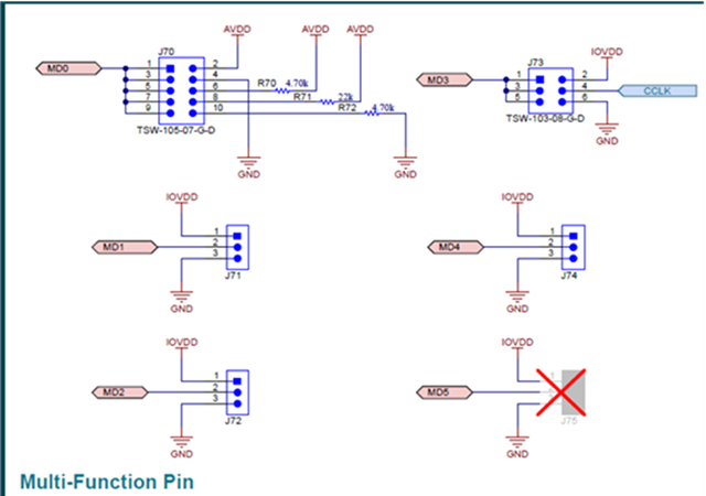
MD0: Short to AVDD (Controller I2S Mode)
MD2:1: 2’b01 (CCLK/128)
MD3: 24.576MHz CCLK input
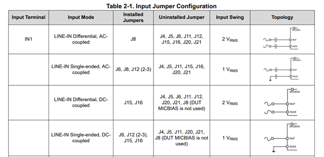
MD5:4: 2’b10 Single-Ended input on INxP; AC-Coupled only

*For measurement, the Digital Serial of the APx555 is connected to the pin header of the External ASI of the EVM.

Best Regards,

Nishie

  • Hi Nishie,

    I tested this myself on an EVM and didn't get the same result - it was still -14dB for the 192k setting you have here. But, I noticed that when MD2 is low and MD1 is high, in TARGET mode, the AVDD is expected to be lower, and maybe this is why you are getting a 2x bigger output here? This is just a theory, since you are using controller mode this should not be the case. 

    Can you share more info about your setup, can you screenshot the entire AP window so I can see which outputs you are using? And attach a picture of how you are connecting to the EVM?

    One more note - if you make changes in your jumpers while the device is connected, it may be in an unknown state, I would recommend disconnecting the USB while you make the changes with jumpers, or doing a power reset between each change.

    Best,
    Mir

  • Hi Mir-san,

    Thank you for your support.

    I tested this myself on an EVM and didn't get the same result - it was still -14dB for the 192k setting you have here. But, I noticed that when MD2 is low and MD1 is high, in TARGET mode, the AVDD is expected to be lower, and maybe this is why you are getting a 2x bigger output here? This is just a theory, since you are using controller mode this should not be the case. 

    ->Thank you for your evaluation on EVM. I understand that there is no problem with the output level in Target mode. Can you check the output level in Controller mode?

    Can you share more info about your setup, can you screenshot the entire AP window so I can see which outputs you are using? And attach a picture of how you are connecting to the EVM?

    One more note - if you make changes in your jumpers while the device is connected, it may be in an unknown state, I would recommend disconnecting the USB while you make the changes with jumpers, or doing a power reset between each change.

    ->The customer is preparing the environment for evaluation. I will contact you once the results are available.

    Also, the input and output conditions of the customer are described.

    Input: DSIO (MCLK24.576MHz, LRCK/BCK Input)
    Output: Analog Unbalance 1 kHz 200mVrms

    Best Regards,

    Nishie

  • Hi Nishie-san,

    I was in controller mode when I did the testing. I had the same setup so I will await your screenshots/pictures and we can keep assessing. Also please include a screenshot of the AP digital serial settings page. I wonder also is this an older version of the chip than I was using? Can you send the marking on the top of the TAA5242 so I can verify?

    Best,
    Mir

  • Hi Mir-san,

    Thank you for testing in controller mode.

    The customer has doubled the gain even in controller mode. I would like to know the reason for this.

    I am attaching a document with a screenshot of the AP window and a picture of the EVM connection  I would appreciate if you could check this.

    TAA5242 MDx setting and Input_Output level_rev2.xlsx

    Best Regards,

    Nishie

  • Hi NIshie-san,

    I will check the connections here tomorrow and get back to you. Sorry about the delay.

    Best,
    Mir

  • Hi Mir-san,

    Thank you for your support.

    Do you have any update?

    Best Regards,

    Nishie

  • Hi Nishie-san,

    I wonder if the optical connection is causing this issue? When I tested I used the DOUT1 header from the AC-MB, next to the BCLK and FSYNC connections. I see you used this for the first pictures, but then the new pictures have optical for the digital output connection. Another note is that in controller mode, the bit depth is always 32, so setting it to 24 on the AP may make the measurements look smaller than we expect.

    Best,
    Mir

  • Hi Mir-san,

    Thank you for checking the picture. There is a correction to the picture.

    The digital output was used when measuring target mode. When measuring controller mode, the AP DSIO and header pin are connected. Sorry for the confusing connection picture.

    The customer will confirm the bit setting.

    Best Regards,

    Nishie

  • Thanks,

    Let me know if changing bit depth helps here.

    -Mir

  • Hi Mir-san,

    The customer changed the bit depth, but the condition did not improve. If there are any other items to check, please let me know. Is it possible that the IC is defective?

    I will report the situation to the customer again.

    ・When Control Mode MD [2:1] = "01," the gain is increased by +6dB compared to other settings.
    ・When Control Mode MD [5:4] = "11," the gain is 6dB lower than when Control Mode MD [5:4] = "10". (It is the same in target mode, so is it a specification?)

    Best Regards,

    Nishie

  • I wonder is this any different when the device is in controller mode for I2S or TDM? 

    I can check again later this week. 

    Best,
    Mir

  • Hi Mir-san,

    1. Did you measure it on the actual machine?

    2. The customer measured the difference between I2S and TDM.

    For TDM, output was only available when Fs=96kHz@24.576MHz was set. Therefore, we measured it only when Fs=96 kHz. Attached is a document that summarizes the results.

    TAA5242 MDx setting and Input_Output level_rev3.xlsx

    The result is the same level as that of I2S. There seems to be no difference between I2S and TDM. Would it be possible for you to measure this result on the actual machine?

    Best Regards,

    Nishie

  • Hi Nishie-san,

    I will be out this coming week so reassigning to my colleague for verification here. But yes, we were measuring with the same EVM you are as well as the same APx555.

    -Mir

  • Hi Yuta,

    Apologies for the delay, I will review your configuration by end of day

  • Hi Daveon-san,

    Thank you for your support.

    Please let me know if there is an update.

    Best Regards,

    Nishie

  • I apologize for the delay, I am still reviewing and if I have no comment I can do a bench test on this device tomorrow.

  • Hi Deveon-san,

    I would appreciate it if you could review and conduct a bench test.

    Best Regards,

    Nishie

  • Hi Yuta,

    Your observations are correct. When you adjust the MD4/MD5 pin to set the common mode tolerance this will change the effective full scale range of the ADC input and degrade SNR performance. 

    This is illustrated for hardware controlled devices in table 2-3, table 2-5, and explained in section 1 of this application note: https://www.ti.com/lit/pdf/slaaeg6

    Additionally, in table 2-4 of the EVM's user guide there are limitations noted for sampling rate and ratios supported in controller mode. https://www.ti.com/lit/pdf/slau904

  • Hi Daveon-san,

    Thank you for confirming the MD4:5 pin and sending the material. I will tell the customer what you told me.

    Also, could you confirm the reason why there was no difference between I2S and TDM and why the gain increased in control mode MD [2: 1]?

    2. The customer measured the difference between I2S and TDM.

    For TDM, output was only available when Fs=96kHz@24.576MHz was set. Therefore, we measured it only when Fs=96 kHz. Attached is a document that summarizes the results.

    TAA5242 MDx setting and Input_Output level_rev3.xlsx

    The result is the same level as that of I2S. There seems to be no difference between I2S and TDM. Would it be possible for you to measure this result on the actual machine?

    ・When Control Mode MD [2:1] = "01," the gain is increased by +6dB compared to other settings.

    Best Regards,

    Nishie

  • Hi Daveon-san,

    I have additional questions.

    TAA5242_Questions_20250804.xlsx

    1. 

    This is illustrated for hardware controlled devices in table 2-3, table 2-5, and explained in section 1 of this application note: https://www.ti.com/lit/pdf/slaaeg6

    ->Could you please confirm Q1 in the attached document?

    In the application note, it is described that the full scale range changes depending on whether it is in High Common Mode or not, but in the EVM manual, it is described that the range does not change (1Vrms). Which is correct, the application note or the EVM manual?

    2.

    Additionally, in table 2-4 of the EVM's user guide there are limitations noted for sampling rate and ratios supported in controller mode. https://www.ti.com/lit/pdf/slau904

    ->Could you please confirm Q2 in the attached document?

    If it is not TDM but I2S, I think there is no limitation under the conditions used in the test (MCLK 24.576 MHz, Fs=192 kHz). Please tell me specifically about the items that are limited.

    Best Regards,

    Nishie

  • Hi Nishie-san,

    Daveon is out of office so I am jumping in to support. 

    ->Could you please confirm Q1 in the attached document?

    In the application note, it is described that the full scale range changes depending on whether it is in High Common Mode or not, but in the EVM manual, it is described that the range does not change (1Vrms). Which is correct, the application note or the EVM manual?

    The table you provided from the EVM manual (Table 2-1. Input Jumper Configuration) does not display any rows for High Common Mode, but only shows the different jumper configurations for AC coupled versus DC coupled modes. The box you outlined in blue does not necessarily represent MD5-4=11 configuration as you suggest. This is why the full-scale value 1Vrms is the same between the red and blue boxes. Higher common mode tolerance will affect full-scale input voltage.

    ->Could you please confirm Q2 in the attached document?

    If it is not TDM but I2S, I think there is no limitation under the conditions used in the test (MCLK 24.576 MHz, Fs=192 kHz). Please tell me specifically about the items that are limited.

    The only sampling rate limitations are listed in the table, and the conditions you used seem to follow. Ensure that BCLK is at least 64Fs (12.288MHz) for 2 channel and 32 bit depth measurement. (min. BCLK = # channels * bit depth * Fs)

    Daveon will return later this week and can support if you have further questions.

    Best,

    Garret

  • Hi Garret-san,

    Thank you for your support.

    I understand that it is a specification that the input range changes by setting MD [5:4].

    Regarding the inquiry that the gain changes by MD [2:1] = "01," I am wondering why the gain changes if the sampling rate Fs=192 kHz is also supported.
    I am sorry, but please follow this matter again.

    Best Regards,

    Nishie

  • Hi Nishie-san,

    Have you been able to recreate this issue on another board? We have yet to see the issue you are describing on our EVM. Using the settings and connections you provided, the gain should be 0dB at full-scale for all sampling frequencies. What are the gain measurements for other sampling frequencies? What is your input? I am continuing to investigate this issue.

    Best,

    Garret

  • Hi Garret-san,

    Since I have only one EVM, I cannot evaluate other EVMs. Is it possible that the IC of the current EVM is broken?

    The gain did not change even if I changed the sampling frequency and MCLK (CCLK). Make the following settings (1) and (2), and (2) will increase the gain by +6dB compared to (1) at any frequency.

    (1) MD [2:1] = 2’b00, 2’b10, 2’b11 (-20dB)

    (2)MD [2:1] = 2’b01 (-14dB)

    Also, AVDD was set to +3.3 V, but the gain did not change even if J24 of EVM was set to +1.8 V. (At this time, 3.3 V and 1.8 V voltages are normal.) Previously, you commented that AVDD +1.8 V setting in Target mode should be disabled in Controller mode. Is it possible that it is enabled for some reason?

    Best Regards,

    Nishie

  • Hi Nishie-san,

    I cannot say for sure, but I would prefer to investigate this further before declaring something is wrong with the IC. The AVDD is also likely not the issue as controller mode expects AVDD 3.3V.

    My theory leans more to do with a bit misalignment, as having a signal mismatched by one bit appears as a doubling of gain. I am working on getting a new EVM for this part and may need a few days to try to replicate and confirm the issue.

    Best,

    Garret

  • Hi Garret-san,

    Thank you for getting the new EVM and proceeding with the evaluation. I am waiting for the result.

    Also, in the case of the problem due to bit shift, I am concerned because I assume that the timing inside the IC is off.

    Best Regards,

    Nishie

  • Hi Nishie-san,

    I was exploring this further today and have a couple questions. You attached a photo of your EVM in one of the Excels you sent over showing you have an RCA connector connected to the INxP terminals for input 1 and input 2.

    1. Do those connectors come from the same cable? As a differential pair? If this is the case, they should both be visible on the AP scope.

    2. Is that how your cables were arranged for every measurement you took in the table you sent? I am now starting to wonder if the doubling occurs due to full-scale mismatch between differential and single-ended configurations, as this is more likely than my previous theory. 

    3. Did you change the input jumpers below when changing between differential and single-ended modes?

    I am still waiting on the new EVM to evaluate on, which will hopefully arrive by the middle of next week.

    Best,

    Garret

  • Hi Garret-san,

    1. They are connected separately from the AP's Unbalanced (Lch/Rch).

    2. I understand that the pin for setting differential and single end is only MD [5:4]. Even if MD [5:4] is set to differential or single end fixed, why does the gain change if MD [2:1] is set to CCLK/128?

    3. Test is set to DC coupling jumper setting.

    I changed several jumpers such as MICBIAS and tested, but the situation did not change. Is there a jumper setting in this that changes the gain if MD [2:1] is set to CCLK/128?

    Best Regards,

    Nishie

  • Hi Nishie-san,

    1. Could you send a photo of the AP connection you used?

    2. I'm still looking into this, and awaiting my new EVM to test on. MD[2:1] should not affect the gain by itself.

    3. When you switch between differential and single-ended modes in MD[5:4], do you add jumpers on J6 and J12 to configure the hardware to single-ended too?

    I look forward to your response.

    Best,

    Garret

  • Hi Garret-san,

    1. The connection picture is as follows. The connection with the AP has not been changed.

    2. Please let me know when you get the measurement results of EVM.

    3. Since the inputs are not differential inputs, J6 and J12 (and J7 and J14) are always measured in the MOUNT state. J15, J16, J17, and J18 are always measured in the OPEN state. From these results, could you please tell us if you have any concerns about the cause of this issue?

    Best Regards,

    Nishie

  • Hi Nishie-san,

    Thank you for this clarification and please give me until the end of the week to test (there are some ongoing delivery issues with my EVM).

    Best,

    Garret

  • Hi Garret-san,

    I understand. Please let me know when the EVM arrives and the evaluation is done.

    Best Regards,

    Nishie

  • Nishie-san,

    I received the EVM today and will begin evaluation. I will respond again when I arrive at a conclusion.

    I noticed you said the jumpers are set to DC coupled here:

    3. Test is set to DC coupling jumper setting.

    But the configuration you described here suggests AC coupling mode: 

    J15, J16, J17, and J18 are always measured in the OPEN state

    I also notice that capacitors C4, C5, C6, and C7, which AC couple the inputs, on your board seem disconnected. Did you physically alter the board at all?

    Thanks and Best,

    Garret

  • Hi Garret-san,

    Thank you for starting the evaluation.

    But the configuration you described here suggests AC coupling mode: 

    I apologize for my lack of understanding. Am I correct in understanding that what you have explained so far is related to AC coupling mode, and that the problem this time occurs because the customer's setting is DC coupling mode? Or am I correct in understanding that you will conduct the evaluation in DC coupling mode?

    I also notice that capacitors C4, C5, C6, and C7, which AC couple the inputs, on your board seem disconnected. Did you physically alter the board at all?

    I will check with the customer.

    Best Regards

    Nishie

  • Nishie-san,

    What exactly do you mean by the customer setting is DC mode? Is this a measurement setting? On the EVM, AC/DC coupling is only set by the jumpers J15-18. Since they are all OPEN, the inputs are AC coupled. If there is a mismatch, this could be causing an issue. I can conduct the evaluation in both modes if necessary.

    However, my larger concern now is that the board is damaged, particularly those capacitors I mentioned previously. This would affect the signal integrity of the inputs in AC coupled mode and could be the reason for the unexpected results. I am looking forward to your response on this.

    Best,

    Garret

  • I recommend populating jumpers J15-18 and retaking your measurements in DC coupled mode.

  • Hi Garret-san,

    What exactly do you mean by the customer setting is DC mode? Is this a measurement setting? On the EVM, AC/DC coupling is only set by the jumpers J15-18. Since they are all OPEN, the inputs are AC coupled. If there is a mismatch, this could be causing an issue. I can conduct the evaluation in both modes if necessary.

    ->There was a mistake in my understanding. Please forget this.

    However, my larger concern now is that the board is damaged, particularly those capacitors I mentioned previously. This would affect the signal integrity of the inputs in AC coupled mode and could be the reason for the unexpected results. I am looking forward to your response on this.

    ->I changed from ceramic capacitors to electrolytic capacitors for C4 to C7. Electrolytic capacitors are soldered on the back of the circuit board. I changed to electrolytic capacitors to improve the low frequency audio characteristics of ceramic capacitors.

    I recommend populating jumpers J15-18 and retaking your measurements in DC coupled mode.

    ->I set MD [5:4] =2'b01, 2b'11, and changed MD [2:1]. The result does not change. The gain is 6dB higher only when MD [2:1] =2'b01.

    Best Regards,

    Nishie

  • Hi Nishie-san,

    ->I set MD [5:4] =2'b01, 2b'11, and changed MD [2:1]. The result does not change. The gain is 6dB higher only when MD [2:1] =2'b01.

    This is not the process I was describing. I would like for you to test in DC coupling mode by populating jumpers J15, J16, J17, J18 in order to bypass the hardware changes and isolate the issue to AC coupled mode. These are not the MD pins, those are J71-75. J15-18 are located next to C4-7.

    MD[5:4] pins change the input source (diff/single-ended) and common mode tolerance, not the coupling mode.

    I imagine your issue arises due to the hardware changes made to your board, as I was able to test on my new EVM and could not replicate the gain increase you are seeing by changing MD[2:1]. I recommend getting a new EVM to test on to demonstrate this is not a device issue.

    Best,

    Garret

  • Hi Garret-san,

    Thank you for the evaluation with the new EVM. This problem occurred before the capacitor was changed. Is it possible to change the EVM to a new one?

    This is not the process I was describing. I would like for you to test in DC coupling mode by populating jumpers J15, J16, J17, J18 in order to bypass the hardware changes and isolate the issue to AC coupled mode. These are not the MD pins, those are J71-75. J15-18 are located next to C4-7.

    I apologize for my lack of understanding. In my test, I changed MD while connecting jumpers to J15 to J18. Could you tell me the measurement method I will perform again?

    Best Regards,

    Nishie

  • Hi Nishie-san,

    The measurement method is the same as you did before, by changing the MD pins and measuring the RMS level of the output of the ADC. Can you send a new picture of your board as well as the results for DC measurement?

    Best,

    Garret

  • Hi Garret-san,

    I am sending you a picture of the EVM.

    The measurement results are the same as what I told you before. The gain is 6dB higher only when MD[2:1]=2’b01.

    Best Regards,

    Nishie

  • Hi Nishie-san,

    I have sent you a private message regarding this matter.

    Best,

    Garret

  • Hi Garret-san,

    I sent you a private message. I would appreciate it if you could confirm it.

    In the new EVM, the capacitor is left as it is. The jumper of MD5 was not implemented, so it was implemented at the time of measurement.

    Best Regards,

    Nishie

  • Hi Nishie-san,

    I responded privately. Sorry for the delay as yesterday was a US holiday.

    Best,

    Garret

  • Hi Garret-san,

    I sent you a private message. I would appreciate it if you could confirm it.

    Best Regards,

    Nishie

  • Hi Nishie-san,

    I responded to your message and am continuing to investigate this issue.

    Best,

    Garret

  • Hi Garret-san,

    Thank you for the evaluation.

    I will tell the customer what you told me. I will contact you if there is any progress.

    Best Regards,

    Nishie

  • Hi Garret-san,

    I sent you a private message. I would appreciate it if you could confirm it.

    Best Regards,

    Nishie

  • Hi Nishie-san,

    Did you change the AC-MB when testing the new EVM?

    Best,

    Garret