This thread has been locked.

If you have a related question, please click the "Ask a related question" button in the top right corner. The newly created question will be automatically linked to this question.

TLV320AIC3104: TLV320AIC3104 impedance matching

Part Number: TLV320AIC3104
Other Parts Discussed in Thread: OPA1622

Tool/software:

Hi,

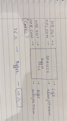
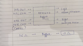
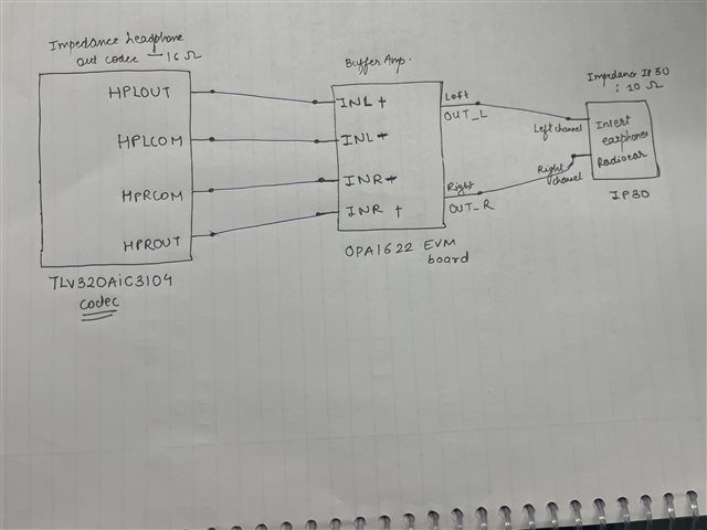
I'm working on an audio project in which I'm facing a problem : my impedance of codec(TLV320AIC3104 stereo  Headphone o/p ) is 16 ohms, I'm using the receiver IP30 from Radio Ear whose impedance is 10 ohms. I need to match the impedance for better performance (Headphone differential output ). Tell me related solution for this problem.  If using a buffer amplifier can be the solution for it then suggest me an IC as well. 

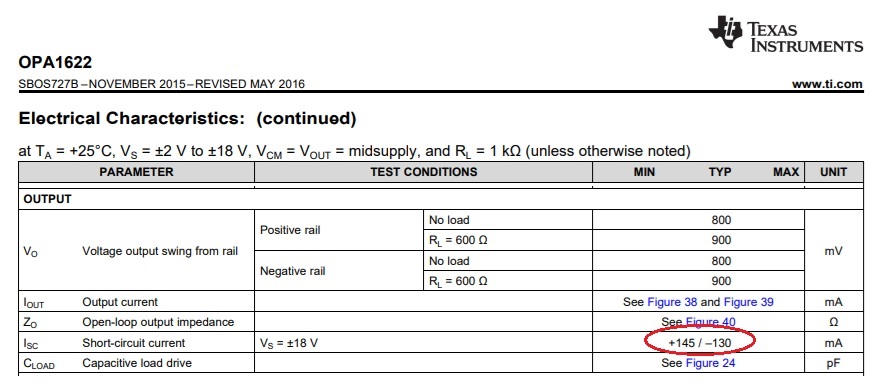
OPA1622  can work with this impedance matching or not ?

Regards,

Falguni Sharma

  • Hi Falguni,

    The simplest option would be to add resistance in series to match the op amp impedance. 

    A buffer amplifier could help but I would need to redirect the ticket to a different team to get you the right recommendation. Let me know if you want to do that.

    Best regards,

    Jeff McPherson

  • Hi,

    Adding resistance in series will not be the efficient solution as I want clean output signal with minimal power loss . Yes you can redirect the ticket to different team .

    Best regards ,

    Falguni Sharma

  • Hi Falguni,

    Sure makes sense. I've passed the ticket along to the op amps team to help you look for a solution.

    Best regards,
    Jeff McPherson

  • Are you concerned about matching input or output impedance? A picture is worth thousand words - in order to assist you please show your circuit schematic. 

  •  I need to match Output impedance,

    In my audio project, input to codec is provided via i2S signal. In the output side of codec TLV320AIC3104 i need to add receiver insert audio phone to take the output signal .

    I need to match the impedance of my codec and receiver as codec impedance is 16 ohm and receiver i chose has impedance of 10 ohm . This 16 and 10 ohm if attached directly will not be efficient for my ouput . Tell me solution how i can achieve this impedance matching .

    Can i use OPA1622(buffer amplifier ) in the output of my codec and then to receiver to match the  impedance . 

    (codec --->Buffer amplifier ---> Receiver )

    Regards ,

    Falguni 

  • I'm not sure I fully follow your description but placing a buffer between codec and receiver will make the input impedance to receiver virtually zero. If you need further assistance, please draw the circuit and use INSERT button below to attach it.

  • Hello TI Team,

    I am working on an audio  project using the TLV320AIC3104 codec. I’m using headphone outputs:

    • HPLOUT / HPLCOM (left channel differential)

    • HPROUT / HPRCOM (right channel differential)

    The receiver I’m using is an IP30 radio ear with 10-ohm impedance. However, the codec's headphone driver has an output impedance of approximately 16 ohms, which creates a mismatch — since the load impedance is lower than the source.

    So tell me how i can solve this problem of impedance matching .

  • I'm really having problem following your description - could you please draw a circuit schematic instead of boxes with labels?   

    Just so you know, placing a buffer between the two nodes makes the output impedance virtually zero.

  • Hi team ,

    I am working on a design where I am using the TLV320AIC3104 codec to drive insert earphones (IP30). The headphone outputs of the codec (HPLOUT, HPROUT) are routed to a buffer amplifier (currently using OPA1622 EVM board as shown in the attached schematic).

    • Codec headphone out impedance: ~16 Ω

    • Earphone impedance: ~10 Ω

    • Buffer amp used: OPA1622

    • Also considering: MAX97220 as an alternative

    My questions:

    1. Will the low output impedance of the buffer amplifier (OPA1622) be sufficient to properly drive IP30 insert earphones?

    2. Between OPA1622 and MAX97220, which would be more suitable for driving low-impedance earphones in terms of audio performance and matching?

  • Falguni,

    Your main challenge in driving 10 ohm load of IP30 will be sufficient output current drive and output swing to the rails and not matching (?).

    OPA1622 has very high output drive (see below typical 145mA/-130mA) so it can drive output to at least +/-1Vp (Iout=+/-1V/10ohm = +/-100mA).

    The open-loop output impedance of OPA1622 is 5.5ohm (see below) at 20kHz but you need to use a close-loop impedance, Zcl=Zo/(1+AOL*beta), to determine attenuation.

    Since AOL is about 66dB (2,000 on linear scale) and for buffer 1/beta is 0db (1 on linear scale), Zcl=5.5ohm/(1+2000*1) =~2.75mohm.

    Thus, the attenuation of the output signal due to finite Zcl will be (0.00275ohm/10ohm)*100%=0.0275%

    Running transient simulation with 1Vp input voltage shows OPA1622 buffer delivering close to +/-100mA current with little attenuation - see below.

    As far as your question regarding MAX97220, its datasheet does not show output impedance nor short-circuit current so it is not possible to make direct comparison regarding performance in for driving low-impedance earphones.  Having said that, OPA1622 supply voltage range is from +/-2V to +/-18V (or 4V to 36V single supply) while MAX97220 2.5V to 5.5V single supply.

    OPA1622 transient with 10ohm load.TSC

  • Hi Marek , 

    Could you please confirm if OPA1622 is fully capable and safe for continuous use with this 10 Ω load, or if there’s a better-suited TI IC for this application?

    Regards ,

    Falguni 

  • Hello, Falguni 

    Yes, if heatsinking removes the heat. That should be easily archivable.

    Maximum current spec is just typical and falls with higher temperature; another reason to keep part cooler.

  • In order to answer your question about reliability, it would be necessary to know what is the supply voltage and the output voltage swing.  Assuming it's 5V single supply with output +/-1Vp between 1.5V to 3.5V (to avoid input common-mode distortion-see below) and load connected to mid-supply (2.5V), the average power dissipation inside the package would be P_avg=IQ*Vcc+Iout_avg*Vdrop = IQ*Vcc + {1Vp/[sq-rt(2)]/10ohm}*(5V-2.5V) = 2.6mA*5V + {0.707V/10ohm}*2.5V = 13mW + 70.7mA*2.5V = 13mW+177mW = 190mW

    Considering the junction-to-ambient thermal resistance is 47.6C/W (see above), this would raise junction temperature above ambient by only 9 degrees (0.19W*47.6C/W), which would be very reliable for the life of the product defined as ten years.  For higher supply voltages, you may need to use bottom heatsink with junction-to-case thermal resistance of 4.1C/W to prevent excessive increase in junction temperature, which could shorten expected life of the product.