This thread has been locked.

If you have a related question, please click the "Ask a related question" button in the top right corner. The newly created question will be automatically linked to this question.

TAC5111: please provide TAC5111 AGC application report document

Part Number: TAC5111

Tool/software:

hi

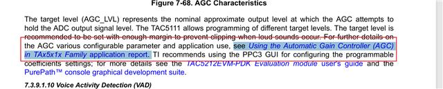
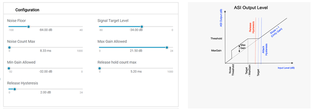
from tac5111 datasheet  chapter 7.3.9.1.9 , user can  download the document "Using the Automatic Gain Controller (AGC) in TAx5x1x Family application report",  but actually it is not for TAx5x1x, please help provide it, now we don't understand the AGC registers means , and also don't konw how to use tac5111 AGC function

  • please help explain the  AGC  ”Noise Floor “ register means and how to evaluate  it's value , please also help explain the difference between  the "Target Level "  and "Maximum Gain" , thanks very much

  • Hi Bert,

    Apologies for the delay.

    The AGC basically applies a gain on the ADC signal in order to hold the output the desired "Target Level".

    The "Maximum Gain" is the maximum gain that can be applied during AGC operation.

    I will follow-up on this thread next week with the other information.

    Thanks and Regards,

    Lakshmi Narasimhan

  • hi Lakshmi Narasimhan

       Do you have any update?

  • Hi Bert,

    The Noise Floor register sets the threshold level used by the AGC to distinguish noise from weak signals. Signals lower than this threshold are classified as noise and not amplified by the AGC.

    The Noise Floor, Target Level and Maximum gain values are programmed as 32-bit coefficient registers. The registers are programmed in dB levels as 22.x fixed-point values.

    Thanks and Regards,

    Lakshmi Narasimhan

  • hi Lakshmi Narasimhan

    Actually I want you provide the document "Using the Automatic Gain Controller (AGC) in TAx5x1x Family application report", can you provide it? 

  • Hi Bert,

    The app note will not be ready to release for another few months at least due to priority items. We can support you in its place. If any parameters are unclear please ask and we can provide an explanation.

    I recommend using PPC3 as a visual to help understand the parameters. You do not need an EVM to use PPC3

    Min Gain is not shown on the plot, but it is effecitvely the same as max gain just in the other direction. If the AGC detects that the gain needs to be reduced below 0 to hit the target level, the gain can be limited on how far below 0 it goes.

    The hold times are also not shown on the plot but these are time sensitive parameters that determine how long of a window is associated with each one

    Noise Hold Count increases the window that calculates if a signal is below the noise threshold or not.
    Release hold count determines how long the gain will be released to 0 once the signal is at the target level before attacking again.

    PPC3 will show you all the available parameters for adjusting, the units associated with each one, and the PPC3 I2C logger tool will capture all the coefficient values associated with any change you make.

    Best regards,
    Jeff McPherson