This thread has been locked.

If you have a related question, please click the "Ask a related question" button in the top right corner. The newly created question will be automatically linked to this question.

TLV320ADC6140: TLV320ADC6140 saturates and wraps codes at half the expected 2 Vrms differential input amplitude.

Part Number: TLV320ADC6140

Tool/software:

Hi,

I've been working on hardware based on the TLV320ADC6140 and noticed the ADC saturates at half the expected input amplitude.
This is on the ADC6140-EVM-PDK evaluation board (though connected via TDM to a custom microcontroller board that acquires the data. (I did think of reproducing it with the EVM doing the data acquisition too, but the board woke up today and decided to not get detected by PPC3 anymore).
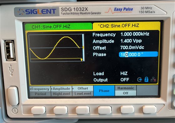
Table 7.5 on page 7 says the "Differential input full-scale AC signal voltage" is 2 Vrms. 2 Vrms would imply that both differential inputs can receive from 0 to 2.75 V, (which corresponds to an amplitude of about 1.4 V or 1 Vrms per input, so 2 Vrms differential). However, the ADC appears to wrap the codes at half of this value, so at differential input of 1 Vrms (1.4 Vpp per input), or when I inject 2.75V amplitude into just one of the differential inputs. 
My first intuition was that this could be somehow caused by improper conversion/signedness somewhere. I verified some stuff related to this and I don't think that's what's going on.
I'm using the 32 bit word length and assuming (because the datasheet doesn't mention this) little-endian, signed integer codes.
Please find attached a screenshot with all the settings that were used to produce this behavior. The signal was injected from an AWG, tested both in AC coupling mode and DC coupling mode.
Happy to provide any further details.
  • Hi Alan,

    Can you share the schematic of the ADC section, to have a look at the inputs being provided to the ADC?

    Also, to confirm the configuration, can you provide a readback dump of all the registers configured?

    Thanks and Regards,

    Lakshmi Narasimhan

  • The ADC is on the EVM board, so the schematic is on page 21 of this: www.ti.com/.../sbau335.pdf

    I connected an AWG to IN1 differentially and generated 1 kHz, 1.4 Vpp on each channel (with some 0.7 Vdc offset, but it's AC coupled), 180deg offset between channels.

    This is the recording waveform of me enabling the first channel of the AWG and then the other one. (I also verified the raw samples reach those close to +- 2^31 values). In the second half of the recording we are almost reaching fullscale, but each input is only receiving 1.4 Vpp, so 1 Vrms differential amplitude.

    Here's the register dump after init. 

    I (4728) ADC_ASI_OUT_CH_EN: 10000000
    I (4768) ADC_ASI_CFG0: 00110000
    I (4808) ADC_ASI_CFG1: 00000000
    I (4848) ADC_ASI_CFG2: 00000000
    I (4888) ADC_DSP_CFG0: 00000000
    I (4928) ADC_DSP_CFG1: 00000000
    I (4968) ADC_IN_CH_EN: 10000000
    I (5008) ADC_ASI_CH1: 00000000
    I (5048) ADC_ASI_CH2: 00000001
    I (5088) ADC_CH1_CFG0: 00000100
    I (5128) ADC_CH2_CFG0: 00000000
    I (5167) ADC_CH1_CFG1: 00000000
    I (5207) ADC_CH2_CFG1: 00000000
    I (5247) ADC_SHDN_CFG: 00110101
    I (5287) ADC_BIAS_CFG: 00000000
    I (5327) ADC_PWR_CFG: 11100000

    Thank you,

    Alan

  • Hi Alan,

    One possible reason for the code wrap at half the rated full-scale could be a mismatch in the ASI output configuration. I see that you have wired out the ASI lines from an external controller to the EVM. The ASI_CFGx values indicate that device is programmed for TDM protocol with TX_OFFSET = 0. If, say, the external controller is sourcing I2S signals, or is expecting a 1 clock of TX_OFFSET, that can result in a bit shift, eventually causing code wrap.

    If you are using EVM, you would be having the ACMB as well. Considering that the ACMB provides TDM signals, you should not see the code wrap if this indeed is the root cause. You can:

    1) Verify the recording with ACMB + EVM, using the above configuration

    2) Verify that the protocol programmed to the device in ASI_CFG0 (TDM, I2S, LJ) matches the signals provided to the BCLK/FSYNC pins from the external controller.

    Thanks and Regards,

    Lakshmi Narasimhan

  • Hi Lakshmi, 

    This was it. I changed ASI_CFG1 to add that 1 BLCK TX_OFFSET and it works perfectly. The TDM driver lib I was using defaulted to the offset protocol and I hadn't realized that. Thank you so much for your help!