TLV320AIC3105EVM-K: Bus Error issue

Part Number: TLV320AIC3105EVM-K
Other Parts Discussed in Thread: TLV320AIC3105

Tool/software:

Hi Sir,

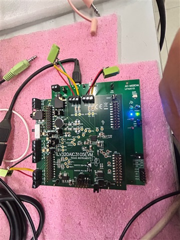
My customer followed the TLV320AIC3105EVM-K user guide and TLV320AIC310xEVM-K GUI tool to do the configuration.

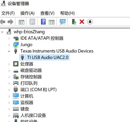
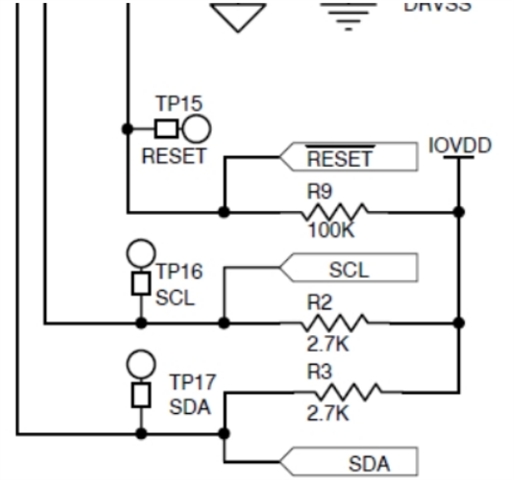
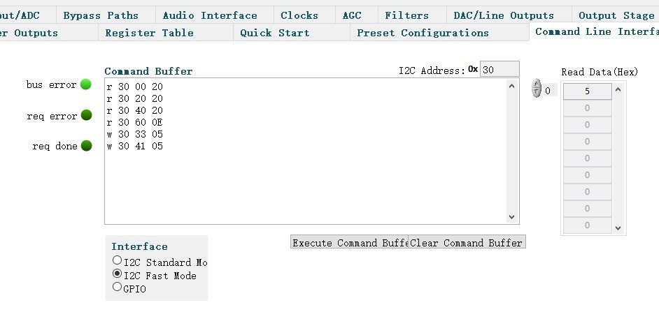
After they configured the channel setting in the EVM and the GUI, the command line always showed the text "bus interface error!", and the EVB's USB Ready LED flashed once. This issue persists even after a software or hardware reset.

In the status, they continued to do the following test item-1 and item-2, the sound channel and found the sound cuts off after about one second, and the EVM itself does a power reset.

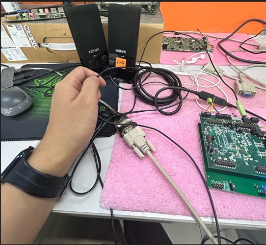
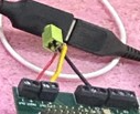
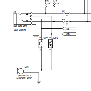
Test item-1, used TLV320AIC3105EVM-K J8(Ext Mic-in) and J9(Headset Output) to do the sound test. The configuration is as follows:

Test item-2, used the J14 to test the Line2 internal bypass channel configuration. The configuration is as follows:

May I know how to check any EVB settings or GUI settings to fix these issues?

  • Hi,

    It sounds like it may be an issue with your connections to the board, or a power issue. You are using the AC-MODEVM, correct? Can you share a picture of your jumper connections on the AIC3105 EVM, and how you are connected to the inputs and outputs in your audio test? And how does the EVM show up in your Windows device manager?

    Best,
    Mir

  • Hi Jeffres,

    Yes, I am using the AC-MODEVM. The following image shows the jumpers,

    connections, and audio input/output connections on my EVM board, the display in the Windows Device Manager.

    Also, there is another situation I need to explain to you:

    Initially, when I followed the documentation to adjust the channels, the EVM board did not respond. After measuring the SDA and SCL lines on the EVM board, I found that every time I sent a command, my SDA line would be pulled low. Even after I stopped sending commands, the SDA line remained stuck low and could not recover.

    I then adjusted the IOVDD voltage to 1.8V (it was initially set to 3.3V) as shown in the image. After that, when I sent commands again, the SDA line was no longer pulled low during measurements. Furthermore, waveform changes were observed every time a command was sent.

    The IOVDD modification was done on the EVM board by changing Jumper 16 from being connected across pins 2-3 to being connected across pins 1-2.

    By the way, could this modification be related to the problem my EVM board is currently experiencing?

    Best Regards,

    Erioe

  • Hi Erioe,

    The IOVDD should be matched across both the AC-MODEVM and the 3105 EVM. JMP16 is on the AIC3105 EVM and I see J4 on your AC-MODEVM is set to 1.8V as well. So, you probably had J4 set to 1.8V and the communication would not work until you stepped it down on the device side as well. Did this fix your original issue of device shutdown or is it still shutting down after playing for a second?

    Best,
    Mir

  • Hi Mir,

    I adjusted J4 to 3.3V and also restored Jumper16 to 3.3V. The observed results are that I2C read and write operations are normal, and the SDA line is not being pulled low. Moreover, after enabling the audio channel, sound is produced normally, but it keeps cutting in and out. My USB Ready light dims and brightens intermittently. When I reduce the input volume, the intermittent sound issue improves; when I increase the input volume, the intermittent sound issue worsens. Does this phenomenon appear to be related to power supply issues? How should I handle this?

    Best Regards,

    Erioe

  • Hi Erioe,

    Sounds like either a power supply issue or an output driver problem, like you are pulling too much current. Since this is USB powered, I would guess it is an output driver problem. I see in your pictures you have a connection to multiple output terminals, which one do you intend? HP out or line out? The "Left Out" and "Right Out" connections are for line, and HPL/HPR are for headphone. Also, can you post your register settings that you are using to get this intermittent output? This will tell us which driver the device thinks it is using.

    Best,
    Mir

  • Hi Mir

    I used two sets of channels for testing, but not simultaneously. The first set takes input from MIC/LINE2 IN (J14) and outputs to HEADSET OUTPUT (J9), with the specific register configurations: 0x2D:0x83; 0x3E:0x83; 0x33:0x3D; 0x41:0x3D. The second set takes input from EXT MIC IN (J8) and still outputs to J9, with the register configurations: 0x0F:0x00; 0x10:0x00; 0x11:0x3F; 0x12:0x3F; 0x13:0x7C; 0x16:0x7C; 0x33:0x3D; 0x41:0x3D; 0x2E:0x80; 0x3F:0x80.

    Best Regards,

    Erioe

  • Hi,

    Does it shut down for both of these configurations? Can you read registers 94-97, these will tell us if it detected a short circuit anywhere on your inputs/outputs? Also, if you are doing analog bypass from your registers 2e and 3f in your second configuration, you do not need the ADCs on, just the PGA. Another thing - make sure your jacks are connected the way you expect, with the L and R channels on the tip and ring, and the sleeve is ground. You may want to check your connections with a multimeter from your jack to the board. 

    The reason I was asking about your outputs is because of this: 

    I noticed that you have a jack connected to the LEFT OUT/RIGHT OUT and some other connection to the HPR jack. Have you changed this to J9?

    Also, you will want to disconnect JMP3 and JMP4, as we can see in the EVM user guide they connect the built in microphone to the IN3L and IN3R lines. 

    Best,
    Mir

  • Dear Mir,

    The shutdown issue is no longer occurring now. There will be some lag in these two scenarios. When I turn up the volume on my PC, the lag becomes more severe; if I turn it down, the lag improves. The values for reg94-97 are 0x0C, 0x00, 0x00, 0x00. The interface currently used for testing output is J9. The LEFT OUT/RIGHT OUT ports in the picture are used as MIC_OUT and also for testing the line1 bypass output.

    Best Regards,

    Erioe

  • Hi Sir,

    Another question in register 93, when the bit D0 = 1 indicates that the Left/RIGHT_LOP/M is fully powered, and the bit D0 = 0 indicates that the Left/RIGHT_LOP/M is not fully powered.
    Why do we write the bit D0 = 0, and we hear the sound output?

    We also found an E2E post mentioned that the d/s has a typo R/W status in registers 86 and 93.

    (+) TLV320AIC3105 LEFT_LOP/M and “RIGHT_LOP/M Power Status datasheet typo ctm Trilogy Communications disty Arrow UK 5-10 Ku/yr opp - Audio forum - Audio - TI E2E support forums

  • Hi Henry,

    Today is a U.S. holiday. Please be patient as our team follows up with you tomorrow.

    Thank you!
    Jeff McPherson

  • Hi,

    What are you writing to register 93 as well as register 86 (Left LOP/M Output Control Register)? I wonder if not just changing D0 but in the process of writing to this register you are also changing D3. You can also read register 94 to check the power status of all output drivers. 

    Also, what do you mean by lag - your computer is lagging? Or the audio is lagging? 

    Best,
    Mir

  • Hi Sir,

    What are you writing to register 93 as well as register 86 (Left LOP/M Output Control Register)? I wonder if not just changing D0 but in the process of writing to this register you are also changing D3. You can also read register 94 to check the power status of all output drivers. => The customer provided the register file. Could you please review it and provide comments?

    TLV320AIC3105 register file: TLV320AIC3105_register_Setting_0903.xls

  • aic3105_mirnotes.xls

    Hi,

    The register settings are likely when the device is not being used for playback so it is not accurate to what happens when there is playback, but if this is a register dump from the middle of the playback, there are some very strange settings that may be causing your issues. It looks like most outputs are powered down. I will attach the same settings with my notes of which registers to look out for to try to understand this issue. The main thing that seems incorrect is that the HPLOUT and HPROUTs are powered up and not muted, but the HPLCOM and HPRCOM outs are not powered up, but the device is set to fully differential headphone out. Also, the dB levels are set differently between differential pairs of HPxOUT and HPxCOM. So, the headphone output drivers are in a weird state and in the status registers it says conflicting info. 

    One more thing that may be causing your output when you turn off the output drivers, is in register 108, it is set to analog bypass from line1RP to RIGHT_LOP and LINE1LP to LEFT_LOP. So, it may be that when the driver is turned off you are getting this analog bypass that seems like the device is passing DAC data out, but it is really an analog input. Let me know what you think.

    Best,
    Mir

  • Hi Sir,

    Since the line 1 bypass is used as the microphone channel, the reg108 is set to 0x11.

    Also, the settings of some registers you mentioned may cause output anomalies. The customer conducted the following experiment on the EVM board.
    Only enabling line 1 bypass in the AIC310X EVM GUI results in audible sound output on the EVM board.

    Setting D0=1, on reg86 and reg93, enable the line 1 bypass; cannot hear sound on the EVM board.

    Setting D0=0, on reg86 and reg93, enable the line 1 bypass; can hear sound on the EVM board.

    Following those test results, the customer thinks that other register settings do not affect the line 1 bypass channel here.

    They believe the problem is determining how to set the correct values in reg86 and reg93.

  • Hi,

    This is strange but I think let's try a few more things. Can you check when you set D0 to 1, can you also set D3 to 1, to unmute the line outputs when you power them up? 

    I think the analog bypass mode will only work if the switch "SW-R0" is open, maybe when the registers 86 and 93 are written to, they close this switch again, or some other signal flow issue is happening when the amplifier is enabled AND the line input switches are closed. I believe if you want to use the analog bypass, you would not be able to set any volume settings on the output. If you want the line input to go to the output with some more control and mixing, you could do a digital bypass, following section 10.4.2 in the datasheet for instructions.

    Best,
    Mir