This thread has been locked.

If you have a related question, please click the "Ask a related question" button in the top right corner. The newly created question will be automatically linked to this question.

TLV320AIC3254: Query on Noise Cancellation and miniDSP usage in TLV320AIC3254

Part Number: TLV320AIC3254


Tool/software:

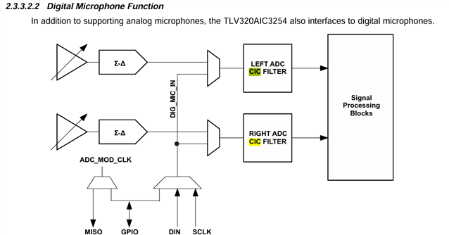
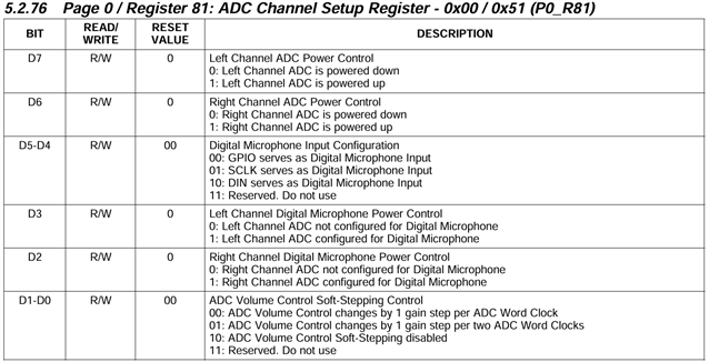
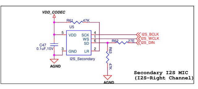
I am working with the TLV320AIC3254 codec in my project. I have two analog microphones and two digital microphones connected to the codec. I want to be able to use either the analog or digital microphones for signal processing.

My requirement is to perform different noise cancellation techniques, such as:

  1. Active Noise Cancellation (ANC)

  2. Acoustic Echo Cancellation (AEC)

  3. Beamforming

  4. Adaptive Filters

    I have a few questions regarding the codec:

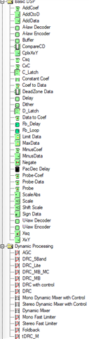
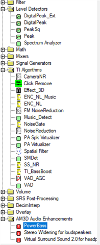
    1. What is the purpose of the processing block and the miniDSP in the TLV320AIC3254? Are these two designed to do the same work, or do they serve different purposes? If different, could you explain what type of operations can be implemented in the processing block versus the miniDSP?

    2. What is the recommended way to use the miniDSP versus the processing blocks in the TLV320AIC3254 in the Pure Path Studio? In which cases should I rely on the built-in processing blocks, and in which cases should I program the miniDSP using PurePath Studio?

    3. From the TI support forums, I found the note:

      • “It cannot keep up with modern expectations of AEC and ANC. We strongly discourage designers from using the DSP in the codec to host the algorithm and instead host the algorithm on a separate DSP or SoC.”
        Based on this, I would like to confirm: Is it correct that advanced algorithms like ANC and AEC cannot be fully supported in the codec’s miniDSP, and are better implemented on an external DSP/SoC?

    4. I also found a note saying:

      • “Adaptive filtering function will not be able to provide noise cancellation. Noise cancellation requires inverting the noise and using it to cancel the noise, rather than just using biquad filtering to filter it out.”
        Could you please clarify this statement in the context of the miniDSP? Does it mean the adaptive filter blocks in the codec are not sufficient for real ANC implementations.

    5. could you please suggest which noise cancellation techniques are practically possible to implement on the TLV320AIC3254 codec itself?
  • Hi,

    I will go through your questions one by one.

    A: The processing blocks are the built-in processing systems available on the device WITHOUT using miniDSP. If you want to use miniDSP, the processing block no longer is used, and vice versa. The main thing the processing blocks are used for is changing the signal chain of how many filters are used as well as if the AGC is able to be enabled. There are some user-programmable biquad filters as well as FIR and IIR filters. You would use a processing block when you are not using miniDSP, and in fact will always be one enabled if miniDSP is not used. MiniDSP is what you would use PurePath Studio to configure. There are of course filters and AGC, but also complex routing is able to be done, and specific algorithms can be run. There are too many options to list, I would recommend you download PurePath Studio (PPS) and see if there are options that you would like to use. Here are some screenshots of the options for the miniDSP algos:

    B: Processing blocks would be if you are not using miniDSP. If you just want some filters, don't use miniDSP. If you want any of the routing or algorithms to use, you can use miniDSP.

    C: Noise cancellation would require another DSP. The miniDSP on the AIC3254 does have a "noise reduction" algorithm, but this will be a rudimentary one made out of filters. Noise cancellation involves playing back an inverted signal and processing, I believe this is too much too fast for the DSP to handle in this device. Most of the interesting algorithms that exist for this device only work at 16kHz sample rate or below, so this also would be too low for an appropriate response in a real AEC/ANC system. There used to be an AEC algorithm in PPS for this device but it has since been removed, I believe it did not work well.

    D: Adaptive filtering is able to be enabled in both miniDSP and processing blocks, I believe. In this device, adaptive filtering is when the filter coefficients can be changed while the device is on and already passing data through. There is a double buffer for the filter coefficients, so when one filter is being used, you can change the coefficients in the other buffer and then switch it over. The idea in a noise cancellation system would be to adapt the filters to cancel out background noise, and adjust it based on a microphone input. However, again this is just filters, and there is some latency for the coefficient buffers switching - and this is not technically noise cancellation, just a noise reduction via filtering. Often background noise is also in the voice band or audio band that you would want to hear, so filtering would also harm the quality of the sound intended. Real noise cancellation inverts the noise so that the signal that is desired can be unaffected.

    E: Mainly filtering-oriented algorithms are most optimal to run on the codec itself, and gain level adjustments. Any of the effects I showed in the screenshots are reasonable to use. I also think miniDSP is useful to route signals through various inputs and outputs through mixers and splitters and such.

    Best,
    Mir

  • Hi,
    Mir

    Thank you for the clear explanation and for clarifying my doubts regarding the noise cancellation techniques of TLVAIC3254 CODEC
    i have another query regarding  Digital Mic Connection and Record/Playback Paths in TLV320AIC3254.

    1.Digital Mic and ADC Connection

          In the reference guide, it shows that digital microphones are attached to the ADC. Since I am using an I²S digital microphone, which already outputs         a digital bitstream, I am confused about the purpose of this connection.

          If the mic already provides digital data, what additional role does the ADC stage have in this case.

    2.Record and Playback Paths
    I would like clarification on the execution of the record and playback paths inside the TLV320AIC3254.

               In which part of the record path are the digital microphones connected

               In which part of the playback path is the digital mic data routed?


  • Hi,

    Typically when we are talking about digital microphones we are talking about PCM digital microphones, not I2S mics. PCM microphones output data that is about the same as the ADC encoded data internal to the device, NOT I2S - it uses the modulator clock as its clock for the digital data. If your microphone outputs I2S, it does not need to go through the ADC at all, instead you would use it as the input to the DAC. 

    Best,
    Mir

  • Hi ,
    Mir 
    Thankyou for the Response.
    I have another query regarding digital microphones. I am using two I²S MEMS microphones (primary – left channel and secondary – right channel). In the TLV320AIC3254 codec, where are these digital microphones connected?


  • Hi,
    Mir

    I have another query regarding the Adaptive Filters. When we enable the adaptive filters through the registers, we load the coefficients into Buffer A, and initially, we also copy the same coefficients into Buffer B.( this is is my assumption, copying the same coefficients of Buffer A in  Buffer B, correct me if i am wrong)

    My question is: while Buffer A is executing in the codec, if we want to modify the coefficients in Buffer B, do we need to manually update the filter coefficients by writing them through registers, or will the codec automatically adjust the coefficients according to the signal characteristics for smooth adaptation?


  • Hi Vandana,

    The device will not update Buffer A or Buffer B on its own. The host must provide the new coefficients to be loaded into the buffer.

    Best regards,
    Jeff McPherson

  • Is my understanding correct that the Digital I²S MEMS microphones connect directly to the miniDSP D ?

  • Hi,

    Yes, if your microphone outputs I2S, then you can connect to the DIN pin and I2S clock pins. DIN pin should be the input to miniDSP D - you will need to use an "I2S IN" block in PPS if you were using PPS.

    Best,
    Mir

  • Thankyou Mir,
    I have a query regarding the clock generation in the TLV320AIC3254 codec.
    I am using the PLL to generate my desired sampling rate, I am not able to be generating the sampling rate(WCLK) and Bit clock.  I have followed the process shown in the attached clock-tree diagram

    Her my MCLK is 12MHZ, and MCLK is the input to PLL_CLKIN.


    i am taking the ADC_MOD_CLK input to BDIV_CLKIN


    i want to generate the sampling rate of 48khz 
    i have configured all register values regarding PLL from reference guide.
    Register - 4      value -0x43
    Register - 5      value -0x91
    Register - 6      value -0x07
    Register - 7      value -0x06
    Register - 8      value -0x90
    Register - 11      value -0x82
    Register - 12     value -0x87
    Register - 13      value -0x00
    Register - 14     value -0x80
    Register - 18      value -0x87
    Register - 19     value -0x82
    Register - 20      value -0x80
    Register - 27      value -0x3c
    Register - 28      value -0x00
    Register - 29     value -0x03
    Register - 30      value -0x88


  • Hi,

    There are a few things you should change here to get the right clocks out. First, register 4 should be set to 0x03, this "high PLL range" is seen in this table from the reference guide:

    With these PLL settings of J.D = 7.1680 or 7.560, the PLL_CLK will be too low for the "high PLL clock range" starting at 92MHz. 

    Next, I would recommend that NDAC=NADC and MDAC=MADC, I see in this example it sets NADC=7 and NDAC=2, and then vice versa for MADC/MDAC. It may be better if you set these to be the same, just in case for future reference if you are using a different clock as an output and get confused why the DAC internal clocks are different than the ADC clocks. It will not affect your specific problem right now since you are using ADC_MOD_CLK as the BCLK divider input, which is after both N and M dividers.

    Finally, if I do the calculation to get what your ADC_MOD_CLK will be -> 12MHz * 7.1680/(7*2) = 6.144MHz. You used BCLK NDIV of 8, so that would be this divided by 8, but since you selected I2S 32 bit, we expect the BCLK to be 48kHz * 32 * 2 = 3.072MHz. So, your BCLK NDIV should be 2 instead (register 30 to 0x82).

    Let me know if this fixes the problem or if you are still having issues.

    Best,
    Mir

  • Hi Mir 
    I wan to know abut the routing of primary i2s interface in TLV320AIC3254 

    I am using two MEMS I²S digital microphones (one Left channel and one Right channel) with the TLV320AIC3254. Both mics are connected to the primary I²S interface of the codec.

    from previous forum ,I understand that the DIN pin is input to miniDSP D.
    My questions are:

    1. How are the Left and Right microphone channels routed through the primary I²S interface into miniDSP D? Do both channels share miniDSP D, or do they get separated internally?

    2. After processing in miniDSP D, are the channels automatically routed such that the Left mic goes to the Left DAC and the Right mic goes to the Right DAC, and then to the headphone outputs?

    3. Could you please clarify the complete signal path: Primary I²S Interface → miniDSP D → DAC  for Left and Right ?


  • Hi,

    The miniDSP can act on any channels separately - miniDSP is programmed with the PurePath Studio software (also called PPS). So, the two channels will stay separated internally and could have separate processing applied if configured that way. If you do not need special features of miniDSP, I would recommend you just use the built-in processing blocks as the "DSP" (processing blocks allow you to use biquads and other filters but not more complicated algorithms like miniDSP can). Either way, L and R DACs stay separate, and then you need to program I2C to send the DAC output through the headphone outs. Your signal path should be fine, or you can remove the "miniDSP D" part and just leave it as an internal processing block, this makes your programming easier as you can do it all with registers found in the datasheet. You can find example scripts in the application reference guide, starting on page 89: https://www.ti.com/lit/an/slaa408a/slaa408a.pdf 

    This includes the example "DAC Playback Through Class-D Headphone Amplifiers" which is likely what you are looking for. Let me know if you need more help!

    Best,
    Mir

  • Hi Mir ,

    I am working with the TLV320AIC3254 codec. I have connected two I2S digital microphones (one left, one right) to the primary I2S interface of the codec. My goal is to route the microphone audio directly to the headphones (playback path) using the miniDSP.

    Currently, I am testing with only the right channel digital mic connected. I have powered up the right ADC and routed the signal through the right DAC (HPR output).

    My clocks are generated correctly:

    • WCLK = 48 kHz

    • Bit width  = 32 bit
    • BCLK = 3.072 MHz

    I followed the reference document provided earlier and configured the registers accordingly, including some additional registers. However, instead of clear audio, I only get continuous noise at the headphone output.

    From previous forum discussions, I understand that the digital I2S mics should be routed through miniDSP D and then to the DACs for headphone output. Could you please help me understand why I might still be getting only noise?

    I will attach my clock and right ADC configuration code for reference

    clock configuration :
    codec_write(0, 0x01); // selecting page 1
    codec_write(1, 0x08);
    codec_write(2, 0xA1);
    codec_write(123, 0x00);

    k_msleep(20);

    codec_write(0, 0x00); //selecting page 0
    codec_write(4, 0x43);
    codec_write(5, 0x11);

    codec_write(6, 0x08);
    codec_write(7, 0x07);
    codec_write(8, 0x80);
    codec_write(5, 0x91);
    k_msleep(10);

    codec_write(25, 0x03);
    codec_write(11, 0x84);
    codec_write(12, 0x84);
    codec_write(13, 0x00);
    codec_write(14, 0x80);
    codec_write(18, 0x84);
    codec_write(19, 0x84);
    codec_write(20, 0x80);

    codec_write(27, 0x3C);
    codec_write(28, 0x00);
    codec_write(29, 0x05);
    codec_write(30, 0x82);

    I2S digital mic right channel configurations 

    codec_write(0, 0x00); // selecting page 0
    codec_write(60, 0x08);


    codec_write(0, 0x01); // selecting page 1
    codec_write(20, 0x25);
    codec_write(10, 0x03);
    codec_write(13, 0x08);
    codec_write(4, 0x00);

    codec_write(0, 0x00); // selecting page 0
    codec_write(81, 0x20);
    codec_write(53, 0x03);
    codec_write(54, 0x02);
    codec_write(31, 0x00);
    codec_write(32, 0x00);
    codec_write(33, 0x11);

    codec_write(0, 0x01); // selecting page 1
    codec_write(17, 0x0F);
    codec_write(9, 0x10);
    k_msleep(2500);

    codec_write(0, 0x00); // selecting page 0
    codec_write(63, 0x44);
    codec_write(64, 0x08);
    codec_write(66, 0x00);


  • In my implementation I am using Processing Block 8 rather than the  configuring the minidsp path  ( refer the register i have attached)  described in the application reference (starting p. 89 of SLA A408A) to route the digital mic data to the DAC.
     https://www.ti.com/lit/an/slaa408a/slaa408a.pdf 

  • Hi,

    Can you share what the output of your microphone looks like on a scope next to the clocks? And a schematic of your system? Your code seems good at first read through. 

    Best,
    Mir

    • I am working with the TLV320AIC3254 codec and a digital microphone connected to its DIN pin. Below is my hardware configuration:

      • In the schematic, R47 is not mounted and R49 is mounted.

      • The DIN pin of the digital mic is connected both to the TLV320AIC3254 and to the MCU.

      • When I capture mic data directly from the MCU through i2s, I can confirm that the digital microphones are working fine (data looks valid).

      • However, when I route the mic audio to the codec and play it through headphones, I continuously hear noise instead of clean audio.

    • Digital mic → MCU path works fine (data is captured correctly).

    • Digital mic → TLV320AIC3254 → Headphones path gives only noise.

      i am attaching Schematic of the digital mic (secondary channel) and codec connections.


      Here the mic data when routed DIN is routed to MCU 
      a:fff8fac0 fff96700 fff8fb00 fff95d00 fff8fa40
      b:fff8f5c0 fff9b2c0 fff8f500 fff9b040 fff8f440
      a:fff8dd80 fff95ac0 fff8dcc0 fff94400 fff8ddc0
      b:fff8fac0 fffab280 fff8fac0 fffa9bc0 fff8f7c0
      a:fff8df80 fffa3800 fff8e080 fffa4840 fff8e240
      b:fff8ce40 fff9fb80 fff8cf40 fff9fac0 fff8d140
      a:fff90240 fff99fc0 fff90300 fff9ac40 fff90280
      b:fff8e840 fff8bec0 fff8e840 fff8d7c0 fff8e7c0
      a:fff8ee40 fff8f980 fff8ed00 fff8f100 fff8eb40
      b:fff8f780 fff92d00 fff8f940 fff93180 fff8f880
      a:fff8c180 fff8f500 fff8c240 fff8fc40 fff8c280
      b:fff8e000 fff8e400 fff8dfc0 fff8e100 fff8e000
      a:fff8e240 fff8cc80 fff8e200 fff8d240 fff8e240
      b:fff8d180 fff8cbc0 fff8d200 fff8d500 fff8d1c0
      a:fff8e3c0 fff4d740 fff8e500 fff4d040 fff8e640
      b:fff8e5c0 fff74540 fff8e680 fff74580 fff8e680
      a:fff8e300 fff84c00 fff8e500 fff84700 fff8e680
      b:fff8e9c0 fff5e100 fff8ec80 fff5d940 fff8edc0
      a:fff8dd00 fff92d00 fff8de40 fff91600 fff8df80
      b:fff8d8c0 fff8cc80 fff8d940 fff90ec0 fff8dbc0


      above a,b are buffers names

  • Hi,

    It would be more helpful if you could show scope shots with the I2S data along with the clocks at the same time. This is to check the timing, to ensure that the DAC expects the same signal as it is given. But, I did check your data to see what it looks like, and I noticed the value "ff8ee40" was much smaller than the others, is this a spike for noise or did you have a typo? Since this is just 50 samples it would equate to around 1ms if we are at 48k so this is also not a great indicator of the type of noise you are hearing.

    With the outlier value (blue is A, orange is B):

    Without outlier value:

    Best,
    Mir


  • The first scope capture shows the I²S data from the right-channel digital microphone connected to the codec, along with the corresponding clocks


    The second scope capture shows the I²S data from both the left and right channel microphones connected to the TLV320AIC3254 codec, along with the clocks.
    green --- BLCK
    blue ---- WCLK
    yellow ---- left and right audio data

  • Hi,

    If you could share your headphone output part of the schematic that may be helpful as well as the power supply connections.

    There are a few things that may need to be changed in your script, and you can find an example script for the HP path of DAC operation in the application reference guide: https://www.ti.com/lit/an/slaa408a/slaa408a.pdf in page 89 or 91 for class D headphone output (for now, your setup is most similar to the example in page 89, you have selected class AB HP output).

    First, if you can add a software reset at the beginning of your script, this is writing register 1 0x01 in page 0. Then, there are a few things you may want to change:

    1) register 123 -> 0x01 (power up reference when analog blocks are powered)

    2) page 1 register 10 -> 0x00 (power HP drivers with AVDD not LDOIN) 

    Let me know if you see any difference after these registers are written. If you are able to try to run the example scripts that would be good to check as well.

    Best,
    Mir


  • Here is the schematic of the codec. I have tried the register settings suggested in the forum, but I still do not get audio output from the digital microphone.

    • The VDD_SYS supply is at 2.7 V.

    • I also tested the Mixer Amplifier path:

      • IN2L, IN2R → Left MIC PGA → Left Mixer Amplifier → Headphones (HPL + HPR)

      • In this path, I am able to get clean audio from the headphones.

    • This confirms that my headphone path and register configuration for the headphone output are working correctly.

    • In the schematic, R47 is not mounted and R49 is mounted.

    • The DIN pin of the digital mic is connected both to the TLV320AIC3254 and to the MCU.

    • When I capture mic data directly from the MCU through i2s, I can confirm that the digital microphones are working fine ,in the pervious forum i have pasted the data 

    • However, when I route the mic audio to the codec and play it through headphones, I continuously hear noise instead of clean audio.

    • I have attached the scope captures of the digital mic I²S signals (both left and right channels). These waveforms confirm that the digital microphones are working fine.

    • I suspect that the issue is specifically in the signal path from the digital mic to the DAC


  •    
    i am trying to generate Beep generation to know what might be the problem in DAC side .
     i am not able to get the beep sound .
    i have  checked the clocks , clocks are proper 
    WCLK --> 48 KHZ
    BIT CLOCK ---> 3.072 MHZ
    MCLK --->12 MHZ 


       codec_write(
    0, 0x00);       // selcting page 0
        codec_write(60, 0x19);      //  DAC processing block 25

        #if 1
        codec_write(0, 0x44);       // selecting page 44
        codec_write(1, 0x04);       // Adaptive filtering for DAC
        #endif

        // common for ADC and DAC path
        codec_write(0, 0x01);       // selecting page 1
        codec_write(1, 0x08);       // powering up internal AVdd LDO
        codec_write(2, 0xA1);       // Enable Master Analog Power Control
        codec_write(71, 0x31);      // Analog inputs powerup time is 3.1ms
        codec_write(123, 0x00);     // Set the REF charging time to 40ms

        codec_write(20, 0x29);      // pop free: 6 time constants, 6k resistance
        codec_write(10, 0x00);      // Full Chip Common Mode is 0.9V powered up with AVDD supply
        codec_write(12, 0x08);      // Left Channel DAC positive terminal is routed to HPL                
        codec_write(13, 0x08);      //  right Channel DAC positive terminal is routed to HPR
        codec_write(9, 0x30);       //  Power up HPL/HPR drivers
        codec_write(16, 0x0F);      // Unmute HPL driver, 0dB Gain
        codec_write(17, 0x0F);      // Unmute HPR driver, 0dB Gain
       
        codec_write(0, 0x00);      // selecting page 0
        codec_write(65, 0x00);      //  LEFT Digital Volume Control 0 db
        codec_write(65, 0x00);      // RIGHT Digital Volume Control 0 db
        codec_write(63, 0xD6);      // left channel and right channel data to left, right DAC
        codec_write(64, 0x00);      // DAC LEFT AND RIGHT channels are unmuted
       

        codec_write(73, 0x01);
        codec_write(74, 0x77);
        codec_write(75, 0x00);
        codec_write(76, 0x23);
        codec_write(77, 0xFB);
        codec_write(78, 0x7A);
        codec_write(79, 0xD7);
        codec_write(71, 0x84);      // VOLUME -4DB
        codec_write(72, 0x04);      // beep enabled

    even i tried this script modifcations , its not working for me .
    e2e.ti.com/.../faq-tlv320aic3254-tlv320aic32xx-family-beep-generator-configuration
  • Hi,

    From your tests apart from beep generator, I think the noise you are hearing may be bit-shifted I2S data - since I2S on this device expects the data to come after 1 BCLK cycle after the WCLK changes. If you could share your analog output waveform shape this may help confirm. To fix this, you can add a data offset configuration with page 0 register 28 (0x1c) and see how this affects your analog output. I would suggest starting with 1 BCLK, and if this does not help, try 31 bits to go the other direction. 

    About the beep generator, can you try switching the order of your last two lines, where you set register 72 first (set level) and then register 71 (enable beep)? 

    Best,
    Mir