OPA1632: OPA1632

Part Number: OPA1632

Tool/software:

Hi Tech Support,

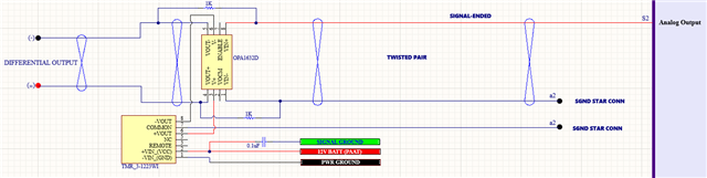
I am in the middle of bench testing this circuit using the OPA1632 chip. I am configuring it as a single ended
analog input with a differential output. When I put a 3V test voltage on the input side, the differential output
goes reads near rail to rail voltage, basically about 28V. Any idea what is going wrong with this circuit.
Do I have something mis-wired. Is the ground reference done properly? Here is the schematic.

  • Hello Mike,

    I am glad to help you out here.  My first observation is you have a 1kOhm resistor as your feedback resistor (RF).  This is okay; I do not see the corresponding gain-setting resistor (RG) which helps to set the gain.

    Depending on what the source impedance of your input signal is, you may be operation the OPA1632 in a high gain, which would result in the amplifier outputs stretching from rail to rail differentially.

    Are you able to add-in an RG resistor into the circuit?  I good example can be found in sections 8.1 & 8.2 of the OPA1632 datasheet, under Application Information.

    Let us start with this debug & move forward from here as we cross-off potential contributors to the amplifier 'railing out.'

    Best,

    Alec

  • Thank you Alec, I will give this a try and add the RG resistor.

  • Hello Mike,

    Great, please let me know how your debug progresses.  Happy to help at any point along the way.

    Best,

    Alec

  • Hi Alec, I am just getting back to this. You recommend adding the RG resistor. Do I need to add the RG resistor to both the inverting and non-inverting inputs? Also, I am looking for a gain of 1, and I already have the 1K resistors in place, do you see any issue if I use 1k ohm for the RG resistor?

  • Hi Mike,

    Great questions; no worries on getting back to me.

    I would suggest keeping the input (source) impedance, gain & feedback resistors, and output impedance matched (symmetric) across both input/output pairs.

    Let me draw up an example circuit for you on Monday/Tuesday if you would like a guide.

    1kOhm is generally good for this device, I will do some analysis if there is a better value we could use.  The larger RG and RF, the larger your input offset current and input bias current (respectively) contributions to overall offset.  This affects DC accuracy, but not as much things as distortion (as in THD).

    Best,

    Alec

  • Hi Alec,

    I realized something about the circuit. I mentioned that I wanted a gain of 1. The reason for this is to have the differential output voltage follow the single-ended input voltage. However, after thinking this over I realized that the positive output would equal the input voltage and also the negative output would be a compliment of the input voltage and this would give me a differential output 2X the single-ended input. For example, if I have a single-ended input of 2V the differential voltage on the output would be 4V. If this is correct, then I would want a gain of 0.5 if I am to have a differential output voltage that equals the single-ended input voltage.

    Thanks for your help with this design Alec!

    Mike

  • I built the circuit with a gain of 1 based on the table 8-1 in the data sheet. The circuit is working now. Thanks for your input Alec! Now I understand the IC much better. The outputs are symmetrical bases on the gain resistor and the VCOM is the dc offset. 

  • Hello Mike,

    Glad you were able to work through the design challenges & interact with a working circuit.  Is there anything else I can help you with at this time?

    Best,

    Alec