OPA1678: microphone output amplification

Part Number: OPA1678

Tool/software:

hi,

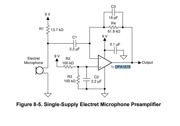
want to amplifies  the output of microphone AOM-5024L-HD-R am planning to use OPA1678 and got some circuit from datasheet .how that below circuit will work for microphone.

  • Hello, 

    I have found a detailed analysis of the microphone you mentioned that can be found here:

    https://diymics.com/why-you-shouldnt-rely-on-microphone-plug-in-power/

    Electret mics have a JFET as a part of the microphone design. For this reason you can use a JFET to model the microphone in simulation. Here is my Tina Ti simulation:

    Electret Example - autosave 25-09-26 07_37.TSC

    I don't have a Tina simulation model for the microphone. For this reason I used one of our discrete JFETs in order to put together a simulation in order to demonstrate how the circuit works. I used 5V for the JFET biasing. For your microphone it is rated at 3V however the link above goes into more details on the biasing of the microphone. The JFET creates an AC current ids that is separate from it's DC current IDS (1.5mA below). The AC current ids flows through the feedback resistor R1 = 61.9k ohm and creates a voltage at the output. The gain is determined by the resistor R1 in the feedback of the op amp. Higher resistors will provide more gain. This is in addition to the gain of the JFET which is determined by the gm or transconductance of the JFET built into the microphone. 

    I hope this information is helpful. 

    Best Regards, 
    Chris Featherstone

  • Dear Chris Featherstone,

    Thanks for sharing the information. I have gained more knowledge about microphones. I still have some questions regarding the above circuits:

    1. What are the criteria for selecting the CD capacitor?

    2. Since I am new to analog circuit design, I found that C1 and R1 act as a low-pass filter. On what basis are these values selected?

    3. If the output of the microphone is given to the inverting terminal, then the op-amp output will be invers of vin right ? If so, does that mean the waveform shown in the image is wrong?

    4. The objective of my project is to detect and analyze the acoustic signature of vehicles from a distance (80 meter).


  • Hi Abhishek,

    Chris is out today but I can help with some quick answers.

    1) CD cap., along with RD, will set the pole that determines where the low-frequency cutoff is, roughly 33 Hz
    2) RD and R1 set the passband gain, and C1 and R1 determine the high-frequency pole.  
    3) There are 2 inversions; one at the JFET, the second from the OPA stage. So, the end result is that there is not a 180 phase shift within the passband.

    I hope this helps.

    Regards,
    Mike