


Tool/software:
Context
I’m using the TLV320ADC5140 with 2 analog microphones and 4 PDM microphones. I read the application note “Analog Microphone and ADC System in Far-field Application” (SBAA395B) - 6) Design of any Microphone with the TLV320ADC51x0/PCM51x0-Q1, but I still have questions about internal routing and channel/slot assignment.
What I understand from the datasheet:
CH1...CH4: full analog front-end (gain, GCAL/PCAL, etc.; CHx_CFG0...CFG4).
CH5...CH8: PDM only (CFG2...CFG4 only).
GPIx/GPOx can be configured each as PDMDIN1...PDMDIN4 and PDMCLK, feeding channel pairs: (CH1–2), (CH3–4), (CH5–6), (CH7–8).
Example (GPI_CFG0 - GPI1_CFG[2:0]):
4d -> PDMDIN1 (CH1/2), 5d -> PDMDIN2 (CH3/4), 6d -> PDMDIN3 (CH5/6), 7d -> PDMDIN4 (CH7/8).
ASI_CHx defines output slots only; it does not change the internal channel bound to the front-end.
Questions
1) PDMDIN on GPI1
Can GPI1 act as PDMDIN1/2/3/4 (feeding CH1/2, CH3/4, CH5/6, CH7/8) regardless of which physical GPI pin is used? In other words, can I set, for example, INP3_GPI3 as PDMDIN4?
Note: this seems to differ from the following figure (likely reconfigurable, so not strictly contradictory, but counterintuitive relative to the diagram).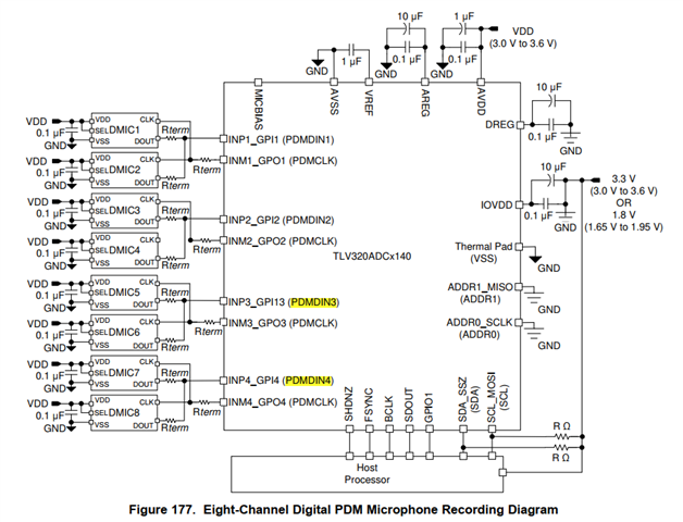
2) Choosing PDMDIN for PDM on IN3/IN4
Setup: IN1/IN2 analog, IN3/IN4 PDM.
To route IN3 → CH5/6 and IN4 → CH7/8, should I program their GPIs as PDMDIN3 and PDMDIN4, respectively?
Note: this would make CH3 and CH4 unusable (you effectively “skip” two channels in the middle).
Alternative:
Would it be better to configure IN3P as PDMDIN2 so it maps to CH3 and CH4, and IN4P as PDMDIN3 so it maps to CH5 and CH6 (leaving CH7 and CH8 unused)?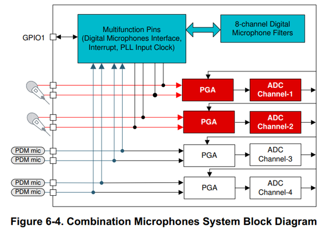
3) Slot assignment when CH3/CH4 are unused
If I use CH1/2 (analog) and CH5-8 (PDM):
-
Is it enough to disable CH3/CH4 in ASI_OUT_CH_EN?
- Even if disabled, should I still avoid slot collisions in ASI_CHx?
Collision example to avoid:
CH1 -> slot 0, CH2 -> slot 1, CH3 -> slot 2 (disabled), CH4 -> slot 3 (disabled), CH5 -> slot 2, CH6 -> slot 3, CH7 -> slot 4, …
Here CH5/CH6 would collide with slots “occupied” by CH3/CH4 even though CH3/CH4 are disabled. - Is it acceptable to push unused channels to the end of the frame and ignore them in software, or is there a recommended approach?
4) Physical design: input - channel binding
If I invert the wiring (PDM on IN1/IN2, analog on IN3/IN4):
-
Do PDM mics then “occupy” CH1...CH4, forcing the analog pair on IN3/IN4 to map to CH5+ and thereby losing the full analog front-end available only on CH1...CH4?
-
More generally, is there any internal mux to reassign an analog pair (e.g., IN3/IN4) to CH1/2, or is the physical input -> CHx binding fixed for channels with the analog front-end?
Concrete example
If I connect PDM on IN1/IN2 and later an analog mic on IN3,
is that analog mic forced to CH5 (unable to map to CH1 with the full front-end)?
5) Possible inconsistency in CHx_CFG0 (INSRC)
CH1...4_CFG0 states:
-
CH1_INSRC: 2d = Digital microphone PDM input (configure the GPO and GPI pins
accordingly for PDMDIN1 and PDMCLK -
CH2_INSRC: 2d = Digital microphone PDM input (configure the GPO and GPI pins
accordingly for PDMDIN1 and PDMCLK) -
CH3_INSRC: 2d = Digital microphone PDM input (configure the GPO and GPI pins
accordingly for PDMDIN2 and PDMCLK) - CH4_INSRC: 2d = Digital microphone PDM input (configure the GPO and GPI pins
accordingly for PDMDIN2 and PDMCLK)
Is this a datasheet typo that limits CH1...4 to PDMDIN1/2? Since GPI_CFG allows selecting PDMDIN1...4 on any GPI, should PDMDIN3/4 also be valid sources for CH1...4?
Relevant registers
-
Page 0: CH1...CH4 -> CFG0...CFG4; CH5..CH8 → CFG2...CFG4 (PDM only).
-
GPI_CFG0/1 (P0_R43/P0_R44): select PDMDIN1...4 and PDMCLK.
-
ASI_CH1...CH8 (P0_R11..P0_R18): output slot assignment.
- ASI_OUT_CH_EN (P0_R116): channel enable.
Thank you in advance!
