


Part Number: TS3A226AE
Tool/software:
I cannot get the microphone to work reliably. If i plug and unplug the headphone jack it may work 4/10 times. Attached is the schematic. Speakers work fine, but i think something is incorrectly implemented on the TS3A226AEYFFR. Any thoughts?
Also, I have to turn up the microphone all the way up to 100% volume to get normal microphone input volume. On the OS microphone test utility in Windows once i turn up the microphone volume to 100% it registers the microphone at around 36. This is the case for the times that it is plugged in and actually works. for the other 6/10 times it doesn't register anything in the microphone test utility.
Thanks,
Jacob
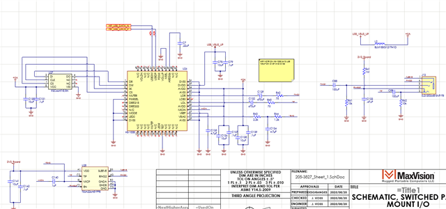

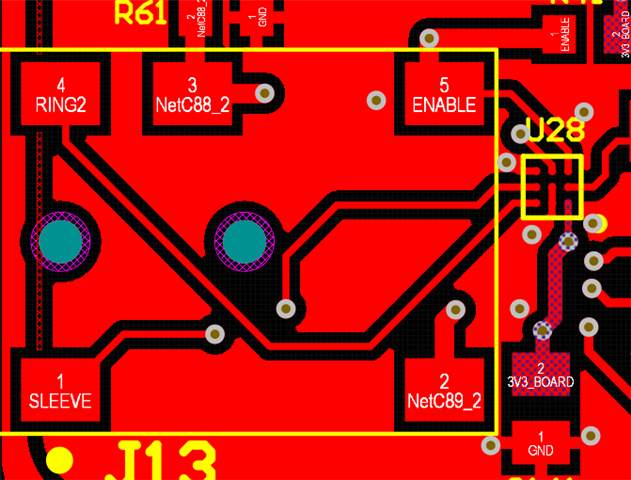
 attached.