TAS2505 Example Sequence

Part Number: TAS2505
Other Parts Discussed in Thread: SYSCONFIG

Tool/software:

Hello Team,

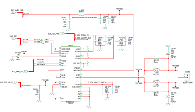
We are trying to integrate TAS2505 DAC with TI AM62Px SOC. Our connection is as follows and we use BCLK and MCLK is not using.

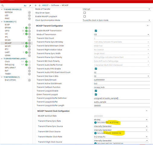
I tried example sequence in ti.com/lit/ug/slau472c/slau472c.pdf?ts=1759243187940 Section 5.1, but this is for setting with MCLK.

Could you please share the correct sequence to be followed for initializing DAC from SOC? The following is our connection.

  • Hi Rakesh,

    Please share your BCLK and WCLK frequencies, then I can give suggestions on how to setup the PLL/Clock tree in TAS2505.

    Best regards,
    -Ivan Salazar
    Applications Engineer

  • Hello  ,

    Thanks for the quick feedback. I am using TI SDK for AM62Px and the configuration in SysConfig is as follows:

    Best Regards,

    Rakesh

  • I'll review your inputs and get back to you tomorrow.

    Best regards,
    -Ivan Salazar
    Applications Engineer

  • Hello ,

    Could you please provide your feedback on the sequence?

    Thanks!

    Regards,

    Rakesh

  • You can try with one of these PLL settings:

    The first example is included in this script; you can add to the rest of your initialization:

    # Page switch to Page 0
    w 30 00 00
    # PLL_CLKIN=BCLK.CODEC_CLKIN=PLL_CLK.BCLK should be 3MHz
    w 30 04 07
    # PLL pwr ON.PLL_P=1.PLL_R=1
    w 30 05 91
    # PLL_J=28
    w 30 06 1c
    # PLL_D=0
    w 30 07 00
    w 30 08 00
    # DAC NDAC Powered up, NDAC=7
    w 30 0b 87
    # DAC MDAC Powered up, MDAC=2
    w 30 0c 82
    # DAC OSR(9:0)-> DOSR=128
    w 30 0d 00
    # DAC OSR(9:0)-> DOSR=128
    w 30 0e 80

    The ratio is the same as if you were using 48kHz and 3.072MHz.

    Best regards,
    -Ivan Salazar
    Applications Engineer

  • Hello  ,

    Thanks for the feedback. If possible, can you share the complete initialization sequence? What we tried  previously is the following:

        TAS2505_WRITE_REG(0x00, 0x00);   /* Page 0 */
        TAS2505_WRITE_REG(0x01, 0x01);   /* Soft reset */
        TAS2505_WRITE_REG(0x00, 0x01);   /* Page 1 */
        TAS2505_WRITE_REG(0x02, 0x00);   /* LDO 1.8V, level shifters ON */
         
        /* --- Back to Page 0: processing + clocks --- */
        TAS2505_WRITE_REG(0x00, 0x00);   /* Page 0 */
        TAS2505_WRITE_REG(0x3C, 0x01);   /* PRB1 */
         
        /* CLOCKING: BYPASS PLL, use MCASP BCLK directly */
        TAS2505_WRITE_REG(0x04, 0x01);   /* CODEC_CLKIN = BCLK */
        TAS2505_WRITE_REG(0x05, 0x00);   /* PLL OFF */
        TAS2505_WRITE_REG(0x06, 0x00);
        TAS2505_WRITE_REG(0x07, 0x00);
        TAS2505_WRITE_REG(0x08, 0x00);
         
        /* SERIAL AUDIO IF: I2S slave, 16-bit word, std polarity */
        TAS2505_WRITE_REG(0x1B, 0x00);
        TAS2505_WRITE_REG(0x1C, 0x00);
        TAS2505_WRITE_REG(0x0B, 0x84);   /* I2S mode, slave */
        TAS2505_WRITE_REG(0x0C, 0x87);   /* 16-bit word */
        TAS2505_WRITE_REG(0x0D, 0x00);
        TAS2505_WRITE_REG(0x0E, 0x80);   /* I2S LR polarity */
         
        /* ROUTING / MIXING: Left DAC from Left data; unmute path */
        TAS2505_WRITE_REG(0x3F, 0xB0);   /* (your path base) */
        TAS2505_WRITE_REG(0x40, 0x00);   /* no attenuation on left mix */
        TAS2505_WRITE_REG(0x41, 0x2F);   /* volume (unmuted) */
         
        /* --- Power up DAC block & set gains --- */
        TAS2505_WRITE_REG(0x00, 0x01);   /* Page 1 */
        TAS2505_WRITE_REG(0x01, 0x10);   /* Power up DAC */
        TAS2505_WRITE_REG(0x03, 0x00);   /* Unmute if this is a global mute */
        TAS2505_WRITE_REG(0x10, 0x1D);   /* DAC gain example */
        TAS2505_WRITE_REG(0x16, 0x00);
        TAS2505_WRITE_REG(0x19, 0x00);
        TAS2505_WRITE_REG(0x2E, 0x00);
        TAS2505_WRITE_REG(0x30, 0x04);
        TAS2505_WRITE_REG(0x2D, 0x02);

    Best Regards,

    Rakesh

  • You can translate the provided snippet into your syntax:

    • w 30 YY ZZ -> TAS2505_WRITE_REG(0xYY, 0xZZ);
    • w 30 = write command to device I2C address 0x30; you don't need these for your own syntax

    Seems you just have to update lines 11 through 15 with the new settings.

    Best regards,
    -Ivan Salazar
    Applications Engineer

  • Thanks Ivan.

    I corrected as follows. Could you please confirm other settings?

       /* --- Reset & rails --- */
        TAS2505_WRITE_REG(0x00, 0x00);   /* Page 0 */
        TAS2505_WRITE_REG(0x01, 0x01);   /* Soft reset */
        TAS2505_WRITE_REG(0x00, 0x01);   /* Page 1 */
        TAS2505_WRITE_REG(0x02, 0x00);   /* LDO 1.8V, level shifters ON */
         
        /* --- Back to Page 0: processing + clocks --- */
        TAS2505_WRITE_REG(0x00, 0x00);   /* Page 0 */
        TAS2505_WRITE_REG(0x3C, 0x01);   /* PRB1 */
         
        /* CLOCKING: BYPASS PLL, use MCASP BCLK directly */
        TAS2505_WRITE_REG(0x04, 0x07);   /* CODEC_CLKIN = BCLK */
        TAS2505_WRITE_REG(0x05, 0x91);   /* PLL OFF */
        TAS2505_WRITE_REG(0x06, 0x1C);
        TAS2505_WRITE_REG(0x07, 0x00);
        TAS2505_WRITE_REG(0x08, 0x00);
         
        /* SERIAL AUDIO IF: I2S slave, 16-bit word, std polarity */
        TAS2505_WRITE_REG(0x1B, 0x00);
        TAS2505_WRITE_REG(0x1C, 0x00);
        TAS2505_WRITE_REG(0x0B, 0x87);   /* I2S mode, slave */
        TAS2505_WRITE_REG(0x0C, 0x82);   /* 16-bit word */
        TAS2505_WRITE_REG(0x0D, 0x00);
        TAS2505_WRITE_REG(0x0E, 0x80);   /* I2S LR polarity */
         
        /* ROUTING / MIXING: Left DAC from Left data; unmute path */
        TAS2505_WRITE_REG(0x3F, 0xB0);   /* (your path base) */
        TAS2505_WRITE_REG(0x40, 0x00);   /* no attenuation on left mix */
        TAS2505_WRITE_REG(0x41, 0x2F);   /* volume (unmuted) */
         
        /* --- Power up DAC block & set gains --- */
        TAS2505_WRITE_REG(0x00, 0x01);   /* Page 1 */
        TAS2505_WRITE_REG(0x01, 0x10);   /* Power up DAC */
        TAS2505_WRITE_REG(0x03, 0x00);   /* Unmute if this is a global mute */
        TAS2505_WRITE_REG(0x10, 0x1D);   /* DAC gain example */
        TAS2505_WRITE_REG(0x16, 0x00);
        TAS2505_WRITE_REG(0x19, 0x00);
        TAS2505_WRITE_REG(0x2E, 0x00);
        TAS2505_WRITE_REG(0x30, 0x04);
        TAS2505_WRITE_REG(0x2D, 0x02);

    Also Is there any possibility to verify if DAC configuration is proper?  (Like to output some test tones?)

    We are seeing MCASP  ISR hits, but no tone in speaker.

    regards

    Rakesh

  • The script has the new settings, that is OK.

    In order to check if the device has the proper configuration, you can play the usual 1kHz sine tone. That gives a clear view of the resulting signal to check if there is distortion, saturation, etc.

    Best regards,
    -Ivan Salazar
    Applications Engineer

  • Hello Ivan

    Thanks for the feedback. How this can be tested?

    This is our connection:

    Do we need to send a 1KHz square wave to DIN pin? How 1KHz sine tone can be given?

    We tried to generate a square pulse from SOC via DIN, but we are not seeing any sound.

    How we can test based on above circuit?

  • TAS2505 is a digital input audio amplifier. The host SoC should send digital signals in I2S or other audio format. A simple square-wave on SDIN won't work.

    To inspect the signal at the output of the amplifier you'll need a low-pass filter, it can be either LC or RC similar to either of these:

    AUX-0025 / 0040 / 0100 Switching Amplifier Measurement Filters | Audio Precision | The Global Leader

    RC Filter Box For Class-D Output Power and THD+N Measurement

    Best regards,
    -Ivan Salazar
    Applications Engineer