This thread has been locked.

If you have a related question, please click the "Ask a related question" button in the top right corner. The newly created question will be automatically linked to this question.

PCMD3140: Channel configuration for PDM input on PPC3

Part Number: PCMD3140


Tool/software:

Hi team,

Wanted to understand what is the best configuration for PCMD3140. I am confused with the pin names since the GUI for ADC3120 and PCMD3140 uses the same one, yet the pin names are different.

I would like to use on-board mic on the EVM, T5818 (MK2). This is connected to IN2P_GPI1 for ADC3120 and PDMDIN1_GPI1 for PCMD3140. Both Pin3.

When opening up PPC3. You are welcomed with the audio inputs. If I want to use PDMDIN1_GPI1 input, which input must be set as PDM? IN1 or IN2?

I am confused since IN1 on ADC3120 should not be able to use PDM input according to the datasheet but it is available.

For audio serial bus, which bus should be enabled? chanel 1 or channel 2?

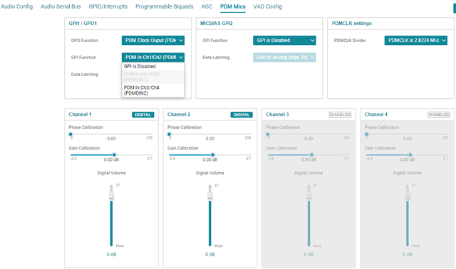
For the PDM Mics section, I think the naming scheme is according to PCMD3140 so below should be fine.

Thanks,
Luke

  • Hi Luke,

    This is what needs to be programmed

    Set both the IN1P/IN1M and IN2P/IN2M inputs to PDM. You're correct that IN1P/M doesn't support PDM clock. This is just the GUI being misleading, because really what you are setting is "Channel 1" and Channel 2" to be PDM, not the input pins themselves. See register 0x3C for an example of what that field sets.

    Go ahead and leave both channels 1 and 2 enabled. Which channel the mic comes in will depend on if you latch the PDM data to the positive or negative edge. Once it works you can just remove the empty channel.

    Yes, you would set GPI1 to be the PDM 1/2 data input. J19 will short the output of the mic to the input of the data pin. J15 shorts the clock output from GPO1 to the clock input of the mic.

    From there everything should work as expected.

    Best regards,
    Jeff McPherson