This thread has been locked.

If you have a related question, please click the "Ask a related question" button in the top right corner. The newly created question will be automatically linked to this question.

TLV320AIC3120EVM-U: Controlling Codec with Microcontroller Through Wiring Instead of USB Connection

Part Number: TLV320AIC3120EVM-U
Other Parts Discussed in Thread: TLV320AIC3120,

Tool/software:

Hello, we are trying to control the TLV320AIC3120 audio codec on the TLV320AIC3120EVM-U board using a Raspberry Pi 4 model b microcontroller over I2C connection so that audio loopback can be achieved with I2S data. The Pi is connected to the codec board through SDA, SCL, MCLK, DIN, BCLK, DOUT, WCLK, and RESET and the respective TP pins on the codec board.

Pinout Details:

I2C Interface:
- SDA: GPIO 2 (Pin 3) -> TP2 (I2C SDA)
- SCL: GPIO 3 (Pin 5) -> TP1 (I2C SCL)

I2S Audio Interface:
- MCLK: GPIO 4 (Pin 7) -> TP3 (MCLK for codec) (Using Fake Clock Because Pi does not provide signals through Mclk)
- BCLK: GPIO 18 (Pin 12) -> TP5 (I2S BCLK)
- LRCLK: GPIO 19 (Pin 35) -> TP7 (I2S WCLK)
- DOUT: GPIO 21 (Pin 40) -> TP4 (I2S DIN to codec)
- DIN: GPIO 20 (Pin 38) -> TP6 (I2S DOUT from codec)

We also physically lifted the IC off the U1 chip TAS1020BPFB to prevent it from communicating over I2C at the same time as the Pi. On the Pi we have installed the correct Linux kernel driver for the codec, and the device is recognized over I2C by the Pi. We also created an overlay file to set up the I2S streaming and MCLK.

Results from i2cdetect:

     0  1  2  3  4  5  6  7  8  9  a  b  c  d  e  f

00:                         -- -- -- -- -- -- -- -- 

10: -- -- -- -- -- -- -- -- UU -- -- -- -- -- -- -- 

20: -- -- -- -- -- -- -- -- -- -- -- -- -- -- -- -- 

30: -- -- -- -- -- -- -- -- -- -- -- -- -- -- -- -- 

40: -- -- -- -- -- -- -- -- -- -- -- -- -- -- -- -- 

50: 50 -- -- -- -- -- -- -- -- -- -- -- -- -- -- -- 

60: -- -- -- -- -- -- -- -- -- -- -- -- -- -- -- -- 

70: -- -- -- -- -- -- -- --                         

However, upon testing, it became clear that the codec was not being initialized correctly, and in dmesg these messages were present:

[ 5.245345] tlv320aic31xx: loading out-of-tree module taints kernel.

[ 5.246262] tlv320aic31xx-codec 1-0018: supply HPVDD not found, using dummy regulator

[ 5.246387] tlv320aic31xx-codec 1-0018: supply SPRVDD not found, using dummy regulator

[ 5.246419] tlv320aic31xx-codec 1-0018: supply SPLVDD not found, using dummy regulator

[ 5.246441] tlv320aic31xx-codec 1-0018: supply AVDD not found, using dummy regulator

[ 5.246478] tlv320aic31xx-codec 1-0018: supply IOVDD not found, using dummy regulator

[ 5.246502] tlv320aic31xx-codec 1-0018: supply DVDD not found, using dummy regulator

[   11.740642] tlv320aic31xx-codec 1-0018: aic31xx_wait_bits: Failed! 0x24 was 0xc0 expected 0x0 (0, 0x40, 500000 us)

[   11.740665] tlv320aic31xx-codec 1-0018: ASoC: POST_PMD: ADC event failed: -1

[   13.012677] tlv320aic31xx-codec 1-0018: aic31xx_wait_bits: Failed! 0x24 was 0xc0 expected 0x0 (0, 0x40, 500000 us)

[   13.012700] tlv320aic31xx-codec 1-0018: ASoC: POST_PMD: ADC event failed: -1

[   13.915491] tlv320aic31xx-codec 1-0018: aic31xx_wait_bits: Failed! 0x24 was 0xc0 expected 0x0 (0, 0x40, 500000 us)

[   13.915526] tlv320aic31xx-codec 1-0018: ASoC: POST_PMD: ADC event failed: -1

[   19.208454] tlv320aic31xx-codec 1-0018: aic31xx_wait_bits: Failed! 0x25 was 0x88 expected 0x0 (0, 0x80, 500000 us)

[   19.208480] tlv320aic31xx-codec 1-0018: ASoC: POST_PMD: DAC Left event failed: -1

[   20.212429] tlv320aic31xx-codec 1-0018: aic31xx_wait_bits: Failed! 0x25 was 0x88 expected 0x0 (0, 0x8, 500000 us)

[   20.212453] tlv320aic31xx-codec 1-0018: ASoC: POST_PMD: DAC Right event failed: -1


How can this issue be solved and allow for codec to be controlled by the Pi? The overlay code is below, as are the results from i2cdump. Thank you for your time.

Overlay Code:

/dts-v1/;
/plugin/;

/ {
    compatible = "brcm,bcm2835";

    fragment@0 {
        target = <&i2s>;
        __overlay__ {
            status = "okay";
        };
    };

    fragment@1 {
        target = <&i2c1>;
        __overlay__ {
            #address-cells = <1>;
            #size-cells = <0>;

            tlv320: tlv320aic3120@18 {
                compatible = "ti,tlv320aic3120";
                reg = <0x18>;
                #sound-dai-cells = <0>;
                clocks = <&dummy_clock>;
                clock-names = "mclk";
            };
        };
    };

    fragment@2 {
        target-path = "/";
        __overlay__ {
            dummy_clock: dummy_clock {
                compatible = "fixed-clock";
                #clock-cells = <0>;
                clock-frequency = <11289600>; // 12.288 MHz
                clock-output-names = "dummy-mclk";
            };
            sound {
                compatible = "simple-audio-card";
                simple-audio-card,name = "TLV320AIC3120";
                simple-audio-card,format = "i2s";
                simple-audio-card,bitclock-master = <&cpu_dai>;
                simple-audio-card,frame-master = <&cpu_dai>;
                simple-audio-card,channels-min = <2>;
                simple-audio-card,channels-max = <2>;

                cpu_dai: simple-audio-card,cpu {
                    sound-dai = <&i2s>;
                };

                codec_dai: simple-audio-card,codec {
                    sound-dai = <&tlv320>;
                };
            };
        };
    };
};

I2C dump results:
     0  1  2  3  4  5  6  7  8  9  a  b  c  d  e  f                   0123456789abcdef
00: 00 00 01 66 00 11 04 00 00 00 00 01 01 00 80 80    ..?f.??....??.??
10: 08 00 01 01 80 80 04 00 00 00 01 30 00 00 01 00    ?.?????...?0..?.
20: 00 00 00 00 c0 88 00 00 00 00 00 00 00 00 00 00    ....??..........
30: 00 00 00 02 32 12 02 02 02 11 10 00 01 04 00 04    ...?2??????.??.?
40: 0c 1b 00 00 6f 38 00 00 00 00 00 ee 10 d8 7e e3    ??..o8.....???~?
50: 00 00 80 00 00 00 00 00 7f 00 00 00 00 00 00 00    ..?.....?.......
60: 00 00 00 00 00 00 00 00 00 00 00 00 00 00 00 00    ................
70: 00 00 00 00 00 00 00 00 00 00 00 00 00 00 00 00    ................
80: 00 00 00 00 00 00 00 00 00 00 00 00 00 00 00 00    ................
90: 00 00 00 00 00 00 00 00 00 00 00 00 00 00 00 00    ................
a0: 00 00 00 00 00 00 00 00 00 00 00 00 00 00 00 00    ................
b0: 00 00 00 00 00 00 00 00 00 00 00 00 00 00 00 00    ................
c0: 00 00 00 00 00 00 00 00 00 00 00 00 00 00 00 00    ................
d0: 00 00 00 00 00 00 00 00 00 00 00 00 00 00 00 00    ................
e0: 00 00 00 00 00 00 00 00 00 00 00 00 00 00 00 00    ................
f0: 00 00 00 00 00 00 00 00 00 00 00 00 00 00 00 00    ................

  • Hi,

    Are you also running a default script before you connect with the driver? The error messages are showing that the device had non-default register values at those registers. Can you try to software reset before you connect?

    Best,
    Mir

  • Mir,
    Thank you for the reply. We are not running any script before connecting with the driver, and while a software reset works, upon reboot of the Pi and attempted connection with the driver the codec registers revert to what is displayed in the post.

    Thanks,
    Caleb

  • Hi Caleb,

    What does your boot/config.txt file look like? I wonder if your registers are being set from somewhere else other than the driver itself, or if the driver has been edited. If you can attach your copy of tlv320aic31xx.c and .h that will help us trace these register settings back as well. Another thing that can change registers is asound.state, but this is ALSA settings, and if the driver is not initializing the device correctly it probably isn't making it to a connection with ALSA.

    Let me know about this.

    Best,
    Mir

  • I agree that it is not making it to connection with ALSA. My /boot/firmware/config.txt and driver files are attached.

    // SPDX-License-Identifier: GPL-2.0
    /*
     * ALSA SoC TLV320AIC31xx CODEC Driver
     *
     * Copyright (C) 2014-2017 Texas Instruments Incorporated - https://www.ti.com/
     *	Jyri Sarha <jsarha@ti.com>
     *
     * Based on ground work by: Ajit Kulkarni <x0175765@ti.com>
     *
     * The TLV320AIC31xx series of audio codecs are low-power, highly integrated
     * high performance codecs which provides a stereo DAC, a mono ADC,
     * and mono/stereo Class-D speaker driver.
     */
    
    #include <linux/unaligned.h>
    #include <linux/module.h>
    #include <linux/moduleparam.h>
    #include <linux/init.h>
    #include <linux/clk.h>
    #include <linux/delay.h>
    #include <linux/pm.h>
    #include <linux/i2c.h>
    #include <linux/gpio/consumer.h>
    #include <linux/regulator/consumer.h>
    #include <linux/acpi.h>
    #include <linux/firmware.h>
    #include <linux/of.h>
    #include <linux/slab.h>
    #include <sound/core.h>
    #include <sound/jack.h>
    #include <sound/pcm.h>
    #include <sound/pcm_params.h>
    #include <sound/soc.h>
    #include <sound/initval.h>
    #include <sound/tlv.h>
    #include <dt-bindings/sound/tlv320aic31xx.h>
    
    #include "tlv320aic31xx.h"
    
    static int aic31xx_set_jack(struct snd_soc_component *component,
                                struct snd_soc_jack *jack, void *data);
    
    static const struct reg_default aic31xx_reg_defaults[] = {
    	{ AIC31XX_CLKMUX, 0x00 },
    	{ AIC31XX_PLLPR, 0x11 },
    	{ AIC31XX_PLLJ, 0x04 },
    	{ AIC31XX_PLLDMSB, 0x00 },
    	{ AIC31XX_PLLDLSB, 0x00 },
    	{ AIC31XX_NDAC, 0x01 },
    	{ AIC31XX_MDAC, 0x01 },
    	{ AIC31XX_DOSRMSB, 0x00 },
    	{ AIC31XX_DOSRLSB, 0x80 },
    	{ AIC31XX_NADC, 0x01 },
    	{ AIC31XX_MADC, 0x01 },
    	{ AIC31XX_AOSR, 0x80 },
    	{ AIC31XX_IFACE1, 0x00 },
    	{ AIC31XX_DATA_OFFSET, 0x00 },
    	{ AIC31XX_IFACE2, 0x00 },
    	{ AIC31XX_BCLKN, 0x01 },
    	{ AIC31XX_DACSETUP, 0x14 },
    	{ AIC31XX_DACMUTE, 0x0c },
    	{ AIC31XX_LDACVOL, 0x00 },
    	{ AIC31XX_RDACVOL, 0x00 },
    	{ AIC31XX_ADCSETUP, 0x00 },
    	{ AIC31XX_ADCFGA, 0x80 },
    	{ AIC31XX_ADCVOL, 0x00 },
    	{ AIC31XX_HPDRIVER, 0x04 },
    	{ AIC31XX_SPKAMP, 0x06 },
    	{ AIC31XX_DACMIXERROUTE, 0x00 },
    	{ AIC31XX_LANALOGHPL, 0x7f },
    	{ AIC31XX_RANALOGHPR, 0x7f },
    	{ AIC31XX_LANALOGSPL, 0x7f },
    	{ AIC31XX_RANALOGSPR, 0x7f },
    	{ AIC31XX_HPLGAIN, 0x02 },
    	{ AIC31XX_HPRGAIN, 0x02 },
    	{ AIC31XX_SPLGAIN, 0x00 },
    	{ AIC31XX_SPRGAIN, 0x00 },
    	{ AIC31XX_MICBIAS, 0x00 },
    	{ AIC31XX_MICPGA, 0x80 },
    	{ AIC31XX_MICPGAPI, 0x00 },
    	{ AIC31XX_MICPGAMI, 0x00 },
    };
    
    static bool aic31xx_volatile(struct device *dev, unsigned int reg)
    {
    	switch (reg) {
    	case AIC31XX_PAGECTL: /* regmap implementation requires this */
    	case AIC31XX_RESET: /* always clears after write */
    	case AIC31XX_OT_FLAG:
    	case AIC31XX_ADCFLAG:
    	case AIC31XX_DACFLAG1:
    	case AIC31XX_DACFLAG2:
    	case AIC31XX_OFFLAG: /* Sticky interrupt flags */
    	case AIC31XX_INTRDACFLAG: /* Sticky interrupt flags */
    	case AIC31XX_INTRADCFLAG: /* Sticky interrupt flags */
    	case AIC31XX_INTRDACFLAG2:
    	case AIC31XX_INTRADCFLAG2:
    	case AIC31XX_HSDETECT:
    		return true;
    	}
    	return false;
    }
    
    static bool aic31xx_writeable(struct device *dev, unsigned int reg)
    {
    	switch (reg) {
    	case AIC31XX_OT_FLAG:
    	case AIC31XX_ADCFLAG:
    	case AIC31XX_DACFLAG1:
    	case AIC31XX_DACFLAG2:
    	case AIC31XX_OFFLAG: /* Sticky interrupt flags */
    	case AIC31XX_INTRDACFLAG: /* Sticky interrupt flags */
    	case AIC31XX_INTRADCFLAG: /* Sticky interrupt flags */
    	case AIC31XX_INTRDACFLAG2:
    	case AIC31XX_INTRADCFLAG2:
    		return false;
    	}
    	return true;
    }
    
    static const struct regmap_range_cfg aic31xx_ranges[] = {
    	{
    		.range_min = 0,
    		.range_max = 12 * 128,
    		.selector_reg = AIC31XX_PAGECTL,
    		.selector_mask = 0xff,
    		.selector_shift = 0,
    		.window_start = 0,
    		.window_len = 128,
    	},
    };
    
    static const struct regmap_config aic31xx_i2c_regmap = {
    	.reg_bits = 8,
    	.val_bits = 8,
    	.writeable_reg = aic31xx_writeable,
    	.volatile_reg = aic31xx_volatile,
    	.reg_defaults = aic31xx_reg_defaults,
    	.num_reg_defaults = ARRAY_SIZE(aic31xx_reg_defaults),
    	.cache_type = REGCACHE_RBTREE,
    	.ranges = aic31xx_ranges,
    	.num_ranges = ARRAY_SIZE(aic31xx_ranges),
    	.max_register = 12 * 128,
    };
    
    static const char * const aic31xx_supply_names[] = {
    	"HPVDD",
    	"SPRVDD",
    	"SPLVDD",
    	"AVDD",
    	"IOVDD",
    	"DVDD",
    };
    
    #define AIC31XX_NUM_SUPPLIES ARRAY_SIZE(aic31xx_supply_names)
    
    struct aic31xx_disable_nb {
    	struct notifier_block nb;
    	struct aic31xx_priv *aic31xx;
    };
    
    struct aic31xx_priv {
    	struct snd_soc_component *component;
    	u8 i2c_regs_status;
    	struct device *dev;
    	struct regmap *regmap;
    	enum aic31xx_type codec_type;
    	struct gpio_desc *gpio_reset;
    	int micbias_vg;
    	struct aic31xx_pdata pdata;
    	struct regulator_bulk_data supplies[AIC31XX_NUM_SUPPLIES];
    	struct aic31xx_disable_nb disable_nb[AIC31XX_NUM_SUPPLIES];
    	struct snd_soc_jack *jack;
    	u32 sysclk_id;
    	unsigned int sysclk;
    	u8 p_div;
    	int rate_div_line;
    	bool master_dapm_route_applied;
    	bool master_mode;	/* true if codec is master, false if slave */
    	int irq;
    	u8 ocmv; /* output common-mode voltage */
    };
    
    struct aic31xx_rate_divs {
    	u32 mclk_p;
    	u32 rate;
    	u8 pll_r;
    	u8 pll_j;
    	u16 pll_d;
    	u16 dosr;
    	u8 ndac;
    	u8 mdac;
    	u8 aosr;
    	u8 nadc;
    	u8 madc;
    };
    
    /* ADC dividers can be disabled by configuring them to 0 */
    static const struct aic31xx_rate_divs aic31xx_divs[] = {
    	/* mclk/p    rate  pll: r  j     d     dosr ndac mdac  aors nadc madc */
    	/* 8k rate */
    	{  512000,   8000,	4, 48,   0,	128,  48,  2,   128,  48,  2},
    	{12000000,   8000,	1, 8, 1920,	128,  48,  2,	128,  48,  2},
    	{12000000,   8000,	1, 8, 1920,	128,  32,  3,	128,  32,  3},
    	{12500000,   8000,	1, 7, 8643,	128,  48,  2,	128,  48,  2},
    	/* 11.025k rate */
    	{  705600,  11025,	3, 48,   0,	128,  24,  3,	128,  24,  3},
    	{12000000,  11025,	1, 7, 5264,	128,  32,  2,	128,  32,  2},
    	{12000000,  11025,	1, 8, 4672,	128,  24,  3,	128,  24,  3},
    	{12500000,  11025,	1, 7, 2253,	128,  32,  2,	128,  32,  2},
    	/* 16k rate */
    	{  512000,  16000,	4, 48,   0,	128,  16,  3,	128,  16,  3},
    	{ 1024000,  16000,	2, 48,   0,	128,  16,  3,	128,  16,  3},
    	{12000000,  16000,	1, 8, 1920,	128,  24,  2,	128,  24,  2},
    	{12000000,  16000,	1, 8, 1920,	128,  16,  3,	128,  16,  3},
    	{12500000,  16000,	1, 7, 8643,	128,  24,  2,	128,  24,  2},
    	/* 22.05k rate */
    	{  705600,  22050,	4, 36,   0,	128,  12,  3,	128,  12,  3},
    	{ 1411200,  22050,	2, 36,   0,	128,  12,  3,	128,  12,  3},
    	{12000000,  22050,	1, 7, 5264,	128,  16,  2,	128,  16,  2},
    	{12000000,  22050,	1, 8, 4672,	128,  12,  3,	128,  12,  3},
    	{12500000,  22050,	1, 7, 2253,	128,  16,  2,	128,  16,  2},
    	/* 32k rate */
    	{ 1024000,  32000,      2, 48,   0,	128,  12,  2,	128,  12,  2},
    	{ 2048000,  32000,      1, 48,   0,	128,  12,  2,	128,  12,  2},
    	{12000000,  32000,	1, 8, 1920,	128,  12,  2,	128,  12,  2},
    	{12000000,  32000,	1, 8, 1920,	128,   8,  3,	128,   8,  3},
    	{12500000,  32000,	1, 7, 8643,	128,  12,  2,	128,  12,  2},
    	/* 44.1k rate */
    	{ 1411200,  44100,	2, 32,   0,	128,   8,  2,	128,   8,  2},
    	{ 2822400,  44100,	1, 32,   0,	128,   8,  2,	128,   8,  2},
    	{12000000,  44100,	1, 7, 5264,	128,   8,  2,	128,   8,  2},
    	{12000000,  44100,	1, 8, 4672,	128,   6,  3,	128,   6,  3},
    	{12500000,  44100,	1, 7, 2253,	128,   8,  2,	128,   8,  2},
    	/* 48k rate */
    	{ 1536000,  48000,	2, 32,   0,	128,   8,  2,	128,   8,  2},
    	{ 3072000,  48000,	1, 32,   0,	128,   8,  2,	128,   8,  2},
    	{12000000,  48000,	1, 8, 1920,	128,   8,  2,	128,   8,  2},
    	{12000000,  48000,	1, 7, 6800,	 96,   5,  4,	 96,   5,  4},
    	{12500000,  48000,	1, 7, 8643,	128,   8,  2,	128,   8,  2},
    	/* 88.2k rate */
    	{ 2822400,  88200,	2, 16,   0,	 64,   8,  2,	 64,   8,  2},
    	{ 5644800,  88200,	1, 16,   0,	 64,   8,  2,	 64,   8,  2},
    	{12000000,  88200,	1, 7, 5264,	 64,   8,  2,	 64,   8,  2},
    	{12000000,  88200,	1, 8, 4672,	 64,   6,  3,	 64,   6,  3},
    	{12500000,  88200,	1, 7, 2253,	 64,   8,  2,	 64,   8,  2},
    	/* 96k rate */
    	{ 3072000,  96000,	2, 16,   0,	 64,   8,  2,	 64,   8,  2},
    	{ 6144000,  96000,	1, 16,   0,	 64,   8,  2,	 64,   8,  2},
    	{12000000,  96000,	1, 8, 1920,	 64,   8,  2,	 64,   8,  2},
    	{12000000,  96000,	1, 7, 6800,	 48,   5,  4,	 48,   5,  4},
    	{12500000,  96000,	1, 7, 8643,	 64,   8,  2,	 64,   8,  2},
    	/* 176.4k rate */
    	{ 5644800, 176400,	2, 8,    0,	 32,   8,  2,	 32,   8,  2},
    	{11289600, 176400,	1, 8,    0,	 32,   8,  2,	 32,   8,  2},
    	{12000000, 176400,	1, 7, 5264,	 32,   8,  2,	 32,   8,  2},
    	{12000000, 176400,	1, 8, 4672,	 32,   6,  3,	 32,   6,  3},
    	{12500000, 176400,	1, 7, 2253,	 32,   8,  2,	 32,   8,  2},
    	/* 192k rate */
    	{ 6144000, 192000,	2, 8,	 0,	 32,   8,  2,	 32,   8,  2},
    	{12288000, 192000,	1, 8,	 0,	 32,   8,  2,	 32,   8,  2},
    	{12000000, 192000,	1, 8, 1920,	 32,   8,  2,	 32,   8,  2},
    	{12000000, 192000,	1, 7, 6800,	 24,   5,  4,	 24,   5,  4},
    	{12500000, 192000,	1, 7, 8643,	 32,   8,  2,	 32,   8,  2},
    };
    
    static const char * const ldac_in_text[] = {
    	"Off", "Left Data", "Right Data", "Mono"
    };
    
    static const char * const rdac_in_text[] = {
    	"Off", "Right Data", "Left Data", "Mono"
    };
    
    static SOC_ENUM_SINGLE_DECL(ldac_in_enum, AIC31XX_DACSETUP, 4, ldac_in_text);
    
    static SOC_ENUM_SINGLE_DECL(rdac_in_enum, AIC31XX_DACSETUP, 2, rdac_in_text);
    
    static const char * const mic_select_text[] = {
    	"Off", "FFR 10 Ohm", "FFR 20 Ohm", "FFR 40 Ohm"
    };
    
    static SOC_ENUM_SINGLE_DECL(mic1lp_p_enum, AIC31XX_MICPGAPI, 6,
    	mic_select_text);
    static SOC_ENUM_SINGLE_DECL(mic1rp_p_enum, AIC31XX_MICPGAPI, 4,
    	mic_select_text);
    static SOC_ENUM_SINGLE_DECL(mic1lm_p_enum, AIC31XX_MICPGAPI, 2,
    	mic_select_text);
    
    static SOC_ENUM_SINGLE_DECL(mic1lm_m_enum, AIC31XX_MICPGAMI, 4,
    	mic_select_text);
    
    static const char * const hp_poweron_time_text[] = {
    	"0us", "15.3us", "153us", "1.53ms", "15.3ms", "76.2ms",
    	"153ms", "304ms", "610ms", "1.22s", "3.04s", "6.1s" };
    
    static SOC_ENUM_SINGLE_DECL(hp_poweron_time_enum, AIC31XX_HPPOP, 3,
    	hp_poweron_time_text);
    
    static const char * const hp_rampup_step_text[] = {
    	"0ms", "0.98ms", "1.95ms", "3.9ms" };
    
    static SOC_ENUM_SINGLE_DECL(hp_rampup_step_enum, AIC31XX_HPPOP, 1,
    	hp_rampup_step_text);
    
    static const char * const vol_soft_step_mode_text[] = {
    	"fast", "slow", "disabled" };
    
    static SOC_ENUM_SINGLE_DECL(vol_soft_step_mode_enum, AIC31XX_DACSETUP, 0,
    	vol_soft_step_mode_text);
    
    static const DECLARE_TLV_DB_SCALE(dac_vol_tlv, -6350, 50, 0);
    static const DECLARE_TLV_DB_SCALE(adc_fgain_tlv, 0, 10, 0);
    static const DECLARE_TLV_DB_SCALE(adc_cgain_tlv, -2000, 50, 0);
    static const DECLARE_TLV_DB_SCALE(mic_pga_tlv, 0, 50, 0);
    static const DECLARE_TLV_DB_SCALE(hp_drv_tlv, 0, 100, 0);
    static const DECLARE_TLV_DB_SCALE(class_D_drv_tlv, 600, 600, 0);
    static const DECLARE_TLV_DB_SCALE(hp_vol_tlv, -6350, 50, 0);
    static const DECLARE_TLV_DB_SCALE(sp_vol_tlv, -6350, 50, 0);
    
    /*
     * controls to be exported to the user space
     */
    static const struct snd_kcontrol_new common31xx_snd_controls[] = {
    	SOC_DOUBLE_R_S_TLV("DAC Playback Volume", AIC31XX_LDACVOL,
    			   AIC31XX_RDACVOL, 0, -127, 48, 7, 0, dac_vol_tlv),
    
    	SOC_DOUBLE_R("HP Driver Playback Switch", AIC31XX_HPLGAIN,
    		     AIC31XX_HPRGAIN, 2, 1, 0),
    	SOC_DOUBLE_R_TLV("HP Driver Playback Volume", AIC31XX_HPLGAIN,
    			 AIC31XX_HPRGAIN, 3, 0x09, 0, hp_drv_tlv),
    
    	SOC_DOUBLE_R_TLV("HP Analog Playback Volume", AIC31XX_LANALOGHPL,
    			 AIC31XX_RANALOGHPR, 0, 0x7F, 1, hp_vol_tlv),
    
    	/* HP de-pop control: apply power not immediately but via ramp
    	 * function with these psarameters. Note that power up sequence
    	 * has to wait for this to complete; this is implemented by
    	 * polling HP driver status in aic31xx_dapm_power_event()
    	 */
    	SOC_ENUM("HP Output Driver Power-On time", hp_poweron_time_enum),
    	SOC_ENUM("HP Output Driver Ramp-up step", hp_rampup_step_enum),
    
    	SOC_ENUM("Volume Soft Stepping", vol_soft_step_mode_enum),
    };
    
    static const struct snd_kcontrol_new aic31xx_snd_controls[] = {
    	SOC_SINGLE_TLV("ADC Fine Capture Volume", AIC31XX_ADCFGA, 4, 4, 1,
    		       adc_fgain_tlv),
    
    	SOC_SINGLE("ADC Capture Switch", AIC31XX_ADCFGA, 7, 1, 1),
    	SOC_DOUBLE_R_S_TLV("ADC Capture Volume", AIC31XX_ADCVOL, AIC31XX_ADCVOL,
    			   0, -24, 40, 6, 0, adc_cgain_tlv),
    
    	SOC_SINGLE_TLV("Mic PGA Capture Volume", AIC31XX_MICPGA, 0,
    		       119, 0, mic_pga_tlv),
    };
    
    static const struct snd_kcontrol_new aic311x_snd_controls[] = {
    	SOC_DOUBLE_R("Speaker Driver Playback Switch", AIC31XX_SPLGAIN,
    		     AIC31XX_SPRGAIN, 2, 1, 0),
    	SOC_DOUBLE_R_TLV("Speaker Driver Playback Volume", AIC31XX_SPLGAIN,
    			 AIC31XX_SPRGAIN, 3, 3, 0, class_D_drv_tlv),
    
    	SOC_DOUBLE_R_TLV("Speaker Analog Playback Volume", AIC31XX_LANALOGSPL,
    			 AIC31XX_RANALOGSPR, 0, 0x7F, 1, sp_vol_tlv),
    };
    
    static const struct snd_kcontrol_new aic310x_snd_controls[] = {
    	SOC_SINGLE("Speaker Driver Playback Switch", AIC31XX_SPLGAIN,
    		   2, 1, 0),
    	SOC_SINGLE_TLV("Speaker Driver Playback Volume", AIC31XX_SPLGAIN,
    		       3, 3, 0, class_D_drv_tlv),
    
    	SOC_SINGLE_TLV("Speaker Analog Playback Volume", AIC31XX_LANALOGSPL,
    		       0, 0x7F, 1, sp_vol_tlv),
    };
    
    static const struct snd_kcontrol_new ldac_in_control =
    	SOC_DAPM_ENUM("DAC Left Input", ldac_in_enum);
    
    static const struct snd_kcontrol_new rdac_in_control =
    	SOC_DAPM_ENUM("DAC Right Input", rdac_in_enum);
    
    static int aic31xx_wait_bits(struct aic31xx_priv *aic31xx, unsigned int reg,
    			     unsigned int mask, unsigned int wbits, int sleep,
    			     int count)
    {
    	unsigned int bits;
    	int counter = count;
    	int ret = regmap_read(aic31xx->regmap, reg, &bits);
    
    	while ((bits & mask) != wbits && counter && !ret) {
    		usleep_range(sleep, sleep * 2);
    		ret = regmap_read(aic31xx->regmap, reg, &bits);
    		counter--;
    	}
    	if ((bits & mask) != wbits) {
    		dev_err(aic31xx->dev,
    			"%s: Failed! 0x%x was 0x%x expected 0x%x (%d, 0x%x, %d us)\n",
    			__func__, reg, bits, wbits, ret, mask,
    			(count - counter) * sleep);
    		ret = -1;
    	}
    	return ret;
    }
    
    #define WIDGET_BIT(reg, shift) (((shift) << 8) | (reg))
    
    static int aic31xx_dapm_power_event(struct snd_soc_dapm_widget *w,
    				    struct snd_kcontrol *kcontrol, int event)
    {
    	struct snd_soc_component *component = snd_soc_dapm_to_component(w->dapm);
    	struct aic31xx_priv *aic31xx = snd_soc_component_get_drvdata(component);
    	unsigned int reg = AIC31XX_DACFLAG1;
    	unsigned int mask;
    	unsigned int timeout = 500 * USEC_PER_MSEC;
    
    	switch (WIDGET_BIT(w->reg, w->shift)) {
    	case WIDGET_BIT(AIC31XX_DACSETUP, 7):
    		mask = AIC31XX_LDACPWRSTATUS_MASK;
    		break;
    	case WIDGET_BIT(AIC31XX_DACSETUP, 6):
    		mask = AIC31XX_RDACPWRSTATUS_MASK;
    		break;
    	case WIDGET_BIT(AIC31XX_HPDRIVER, 7):
    		mask = AIC31XX_HPLDRVPWRSTATUS_MASK;
    		if (event == SND_SOC_DAPM_POST_PMU)
    			timeout = 7 * USEC_PER_SEC;
    		break;
    	case WIDGET_BIT(AIC31XX_HPDRIVER, 6):
    		mask = AIC31XX_HPRDRVPWRSTATUS_MASK;
    		if (event == SND_SOC_DAPM_POST_PMU)
    			timeout = 7 * USEC_PER_SEC;
    		break;
    	case WIDGET_BIT(AIC31XX_SPKAMP, 7):
    		mask = AIC31XX_SPLDRVPWRSTATUS_MASK;
    		break;
    	case WIDGET_BIT(AIC31XX_SPKAMP, 6):
    		mask = AIC31XX_SPRDRVPWRSTATUS_MASK;
    		break;
    	case WIDGET_BIT(AIC31XX_ADCSETUP, 7):
    		mask = AIC31XX_ADCPWRSTATUS_MASK;
    		reg = AIC31XX_ADCFLAG;
    		break;
    	default:
    		dev_err(component->dev, "Unknown widget '%s' calling %s\n",
    			w->name, __func__);
    		return -EINVAL;
    	}
    
    	switch (event) {
    	case SND_SOC_DAPM_POST_PMU:
    		return aic31xx_wait_bits(aic31xx, reg, mask, mask,
    				5000, timeout / 5000);
    	case SND_SOC_DAPM_POST_PMD:
    		return aic31xx_wait_bits(aic31xx, reg, mask, 0,
    				5000, timeout / 5000);
    	default:
    		dev_dbg(component->dev,
    			"Unhandled dapm widget event %d from %s\n",
    			event, w->name);
    	}
    	return 0;
    }
    
    static const struct snd_kcontrol_new aic31xx_left_output_switches[] = {
    	SOC_DAPM_SINGLE("From Left DAC", AIC31XX_DACMIXERROUTE, 6, 1, 0),
    	SOC_DAPM_SINGLE("From MIC1LP", AIC31XX_DACMIXERROUTE, 5, 1, 0),
    	SOC_DAPM_SINGLE("From MIC1RP", AIC31XX_DACMIXERROUTE, 4, 1, 0),
    };
    
    static const struct snd_kcontrol_new aic31xx_right_output_switches[] = {
    	SOC_DAPM_SINGLE("From Right DAC", AIC31XX_DACMIXERROUTE, 2, 1, 0),
    	SOC_DAPM_SINGLE("From MIC1RP", AIC31XX_DACMIXERROUTE, 1, 1, 0),
    };
    
    static const struct snd_kcontrol_new dac31xx_left_output_switches[] = {
    	SOC_DAPM_SINGLE("From Left DAC", AIC31XX_DACMIXERROUTE, 6, 1, 0),
    	SOC_DAPM_SINGLE("From AIN1", AIC31XX_DACMIXERROUTE, 5, 1, 0),
    	SOC_DAPM_SINGLE("From AIN2", AIC31XX_DACMIXERROUTE, 4, 1, 0),
    };
    
    static const struct snd_kcontrol_new dac31xx_right_output_switches[] = {
    	SOC_DAPM_SINGLE("From Right DAC", AIC31XX_DACMIXERROUTE, 2, 1, 0),
    	SOC_DAPM_SINGLE("From AIN2", AIC31XX_DACMIXERROUTE, 1, 1, 0),
    };
    
    static const struct snd_kcontrol_new p_term_mic1lp =
    	SOC_DAPM_ENUM("MIC1LP P-Terminal", mic1lp_p_enum);
    
    static const struct snd_kcontrol_new p_term_mic1rp =
    	SOC_DAPM_ENUM("MIC1RP P-Terminal", mic1rp_p_enum);
    
    static const struct snd_kcontrol_new p_term_mic1lm =
    	SOC_DAPM_ENUM("MIC1LM P-Terminal", mic1lm_p_enum);
    
    static const struct snd_kcontrol_new m_term_mic1lm =
    	SOC_DAPM_ENUM("MIC1LM M-Terminal", mic1lm_m_enum);
    
    static const struct snd_kcontrol_new aic31xx_dapm_hpl_switch =
    	SOC_DAPM_SINGLE("Switch", AIC31XX_LANALOGHPL, 7, 1, 0);
    
    static const struct snd_kcontrol_new aic31xx_dapm_hpr_switch =
    	SOC_DAPM_SINGLE("Switch", AIC31XX_RANALOGHPR, 7, 1, 0);
    
    static const struct snd_kcontrol_new aic31xx_dapm_spl_switch =
    	SOC_DAPM_SINGLE("Switch", AIC31XX_LANALOGSPL, 7, 1, 0);
    
    static const struct snd_kcontrol_new aic31xx_dapm_spr_switch =
    	SOC_DAPM_SINGLE("Switch", AIC31XX_RANALOGSPR, 7, 1, 0);
    
    static int mic_bias_event(struct snd_soc_dapm_widget *w,
    			  struct snd_kcontrol *kcontrol, int event)
    {
    	struct snd_soc_component *component = snd_soc_dapm_to_component(w->dapm);
    	struct aic31xx_priv *aic31xx = snd_soc_component_get_drvdata(component);
    
    	switch (event) {
    	case SND_SOC_DAPM_POST_PMU:
    		/* change mic bias voltage to user defined */
    		snd_soc_component_update_bits(component, AIC31XX_MICBIAS,
    				    AIC31XX_MICBIAS_MASK,
    				    aic31xx->micbias_vg <<
    				    AIC31XX_MICBIAS_SHIFT);
    		dev_dbg(component->dev, "%s: turned on\n", __func__);
    		break;
    	case SND_SOC_DAPM_PRE_PMD:
    		/* turn mic bias off */
    		snd_soc_component_update_bits(component, AIC31XX_MICBIAS,
    				    AIC31XX_MICBIAS_MASK, 0);
    		dev_dbg(component->dev, "%s: turned off\n", __func__);
    		break;
    	}
    	return 0;
    }
    
    static const struct snd_soc_dapm_widget common31xx_dapm_widgets[] = {
    	SND_SOC_DAPM_AIF_IN("AIF IN", "Playback", 0, SND_SOC_NOPM, 0, 0),
    
    	SND_SOC_DAPM_MUX("DAC Left Input",
    			 SND_SOC_NOPM, 0, 0, &ldac_in_control),
    	SND_SOC_DAPM_MUX("DAC Right Input",
    			 SND_SOC_NOPM, 0, 0, &rdac_in_control),
    	/* DACs */
    	SND_SOC_DAPM_DAC_E("DAC Left", "Left Playback",
    			   AIC31XX_DACSETUP, 7, 0, aic31xx_dapm_power_event,
    			   SND_SOC_DAPM_POST_PMU | SND_SOC_DAPM_POST_PMD),
    
    	SND_SOC_DAPM_DAC_E("DAC Right", "Right Playback",
    			   AIC31XX_DACSETUP, 6, 0, aic31xx_dapm_power_event,
    			   SND_SOC_DAPM_POST_PMU | SND_SOC_DAPM_POST_PMD),
    
    	/* HP */
    	SND_SOC_DAPM_SWITCH("HP Left", SND_SOC_NOPM, 0, 0,
    			    &aic31xx_dapm_hpl_switch),
    	SND_SOC_DAPM_SWITCH("HP Right", SND_SOC_NOPM, 0, 0,
    			    &aic31xx_dapm_hpr_switch),
    
    	/* Output drivers */
    	SND_SOC_DAPM_OUT_DRV_E("HPL Driver", AIC31XX_HPDRIVER, 7, 0,
    			       NULL, 0, aic31xx_dapm_power_event,
    			       SND_SOC_DAPM_POST_PMD | SND_SOC_DAPM_POST_PMU),
    	SND_SOC_DAPM_OUT_DRV_E("HPR Driver", AIC31XX_HPDRIVER, 6, 0,
    			       NULL, 0, aic31xx_dapm_power_event,
    			       SND_SOC_DAPM_POST_PMD | SND_SOC_DAPM_POST_PMU),
    
    	/* Mic Bias */
    	SND_SOC_DAPM_SUPPLY("MICBIAS", SND_SOC_NOPM, 0, 0, mic_bias_event,
    			    SND_SOC_DAPM_POST_PMU | SND_SOC_DAPM_PRE_PMD),
    
    	/* Keep BCLK/WCLK enabled even if DAC/ADC is powered down */
    	SND_SOC_DAPM_SUPPLY("Activate I2S clocks", AIC31XX_IFACE2, 2, 0,
    			    NULL, 0),
    
    	/* Outputs */
    	SND_SOC_DAPM_OUTPUT("HPL"),
    	SND_SOC_DAPM_OUTPUT("HPR"),
    };
    
    static const struct snd_soc_dapm_widget dac31xx_dapm_widgets[] = {
    	/* Inputs */
    	SND_SOC_DAPM_INPUT("AIN1"),
    	SND_SOC_DAPM_INPUT("AIN2"),
    
    	/* Output Mixers */
    	SND_SOC_DAPM_MIXER("Output Left", SND_SOC_NOPM, 0, 0,
    			   dac31xx_left_output_switches,
    			   ARRAY_SIZE(dac31xx_left_output_switches)),
    	SND_SOC_DAPM_MIXER("Output Right", SND_SOC_NOPM, 0, 0,
    			   dac31xx_right_output_switches,
    			   ARRAY_SIZE(dac31xx_right_output_switches)),
    };
    
    static const struct snd_soc_dapm_widget aic31xx_dapm_widgets[] = {
    	/* Inputs */
    	SND_SOC_DAPM_INPUT("MIC1LP"),
    	SND_SOC_DAPM_INPUT("MIC1RP"),
    	SND_SOC_DAPM_INPUT("MIC1LM"),
    
    	/* Input Selection to MIC_PGA */
    	SND_SOC_DAPM_MUX("MIC1LP P-Terminal", SND_SOC_NOPM, 0, 0,
    			 &p_term_mic1lp),
    	SND_SOC_DAPM_MUX("MIC1RP P-Terminal", SND_SOC_NOPM, 0, 0,
    			 &p_term_mic1rp),
    	SND_SOC_DAPM_MUX("MIC1LM P-Terminal", SND_SOC_NOPM, 0, 0,
    			 &p_term_mic1lm),
    
    	/* ADC */
    	SND_SOC_DAPM_ADC_E("ADC", "Capture", AIC31XX_ADCSETUP, 7, 0,
    			   aic31xx_dapm_power_event, SND_SOC_DAPM_POST_PMU |
    			   SND_SOC_DAPM_POST_PMD),
    
    	SND_SOC_DAPM_MUX("MIC1LM M-Terminal", SND_SOC_NOPM, 0, 0,
    			 &m_term_mic1lm),
    
    	/* Enabling & Disabling MIC Gain Ctl */
    	SND_SOC_DAPM_PGA("MIC_GAIN_CTL", AIC31XX_MICPGA,
    			 7, 1, NULL, 0),
    
    	/* Output Mixers */
    	SND_SOC_DAPM_MIXER("Output Left", SND_SOC_NOPM, 0, 0,
    			   aic31xx_left_output_switches,
    			   ARRAY_SIZE(aic31xx_left_output_switches)),
    	SND_SOC_DAPM_MIXER("Output Right", SND_SOC_NOPM, 0, 0,
    			   aic31xx_right_output_switches,
    			   ARRAY_SIZE(aic31xx_right_output_switches)),
    
    	SND_SOC_DAPM_AIF_OUT("AIF OUT", "Capture", 0, SND_SOC_NOPM, 0, 0),
    };
    
    static const struct snd_soc_dapm_widget aic311x_dapm_widgets[] = {
    	/* AIC3111 and AIC3110 have stereo class-D amplifier */
    	SND_SOC_DAPM_OUT_DRV_E("SPL ClassD", AIC31XX_SPKAMP, 7, 0, NULL, 0,
    			       aic31xx_dapm_power_event, SND_SOC_DAPM_POST_PMU |
    			       SND_SOC_DAPM_POST_PMD),
    	SND_SOC_DAPM_OUT_DRV_E("SPR ClassD", AIC31XX_SPKAMP, 6, 0, NULL, 0,
    			       aic31xx_dapm_power_event, SND_SOC_DAPM_POST_PMU |
    			       SND_SOC_DAPM_POST_PMD),
    	SND_SOC_DAPM_SWITCH("Speaker Left", SND_SOC_NOPM, 0, 0,
    			    &aic31xx_dapm_spl_switch),
    	SND_SOC_DAPM_SWITCH("Speaker Right", SND_SOC_NOPM, 0, 0,
    			    &aic31xx_dapm_spr_switch),
    	SND_SOC_DAPM_OUTPUT("SPL"),
    	SND_SOC_DAPM_OUTPUT("SPR"),
    };
    
    /* AIC3100 and AIC3120 have only mono class-D amplifier */
    static const struct snd_soc_dapm_widget aic310x_dapm_widgets[] = {
    	SND_SOC_DAPM_OUT_DRV_E("SPK ClassD", AIC31XX_SPKAMP, 7, 0, NULL, 0,
    			       aic31xx_dapm_power_event, SND_SOC_DAPM_POST_PMU |
    			       SND_SOC_DAPM_POST_PMD),
    	SND_SOC_DAPM_SWITCH("Speaker", SND_SOC_NOPM, 0, 0,
    			    &aic31xx_dapm_spl_switch),
    	SND_SOC_DAPM_OUTPUT("SPK"),
    };
    
    static const struct snd_soc_dapm_route
    common31xx_audio_map[] = {
    	/* DAC Input Routing */
    	{"DAC Left Input", "Left Data", "AIF IN"},
    	{"DAC Left Input", "Right Data", "AIF IN"},
    	{"DAC Left Input", "Mono", "AIF IN"},
    	{"DAC Right Input", "Left Data", "AIF IN"},
    	{"DAC Right Input", "Right Data", "AIF IN"},
    	{"DAC Right Input", "Mono", "AIF IN"},
    	{"DAC Left", NULL, "DAC Left Input"},
    	{"DAC Right", NULL, "DAC Right Input"},
    
    	/* HPL path */
    	{"HP Left", "Switch", "Output Left"},
    	{"HPL Driver", NULL, "HP Left"},
    	{"HPL", NULL, "HPL Driver"},
    
    	/* HPR path */
    	{"HP Right", "Switch", "Output Right"},
    	{"HPR Driver", NULL, "HP Right"},
    	{"HPR", NULL, "HPR Driver"},
    };
    
    static const struct snd_soc_dapm_route
    dac31xx_audio_map[] = {
    	/* Left Output */
    	{"Output Left", "From Left DAC", "DAC Left"},
    	{"Output Left", "From AIN1", "AIN1"},
    	{"Output Left", "From AIN2", "AIN2"},
    
    	/* Right Output */
    	{"Output Right", "From Right DAC", "DAC Right"},
    	{"Output Right", "From AIN2", "AIN2"},
    };
    
    static const struct snd_soc_dapm_route
    aic31xx_audio_map[] = {
    	/* Mic input */
    	{"MIC1LP P-Terminal", "FFR 10 Ohm", "MIC1LP"},
    	{"MIC1LP P-Terminal", "FFR 20 Ohm", "MIC1LP"},
    	{"MIC1LP P-Terminal", "FFR 40 Ohm", "MIC1LP"},
    	{"MIC1RP P-Terminal", "FFR 10 Ohm", "MIC1RP"},
    	{"MIC1RP P-Terminal", "FFR 20 Ohm", "MIC1RP"},
    	{"MIC1RP P-Terminal", "FFR 40 Ohm", "MIC1RP"},
    	{"MIC1LM P-Terminal", "FFR 10 Ohm", "MIC1LM"},
    	{"MIC1LM P-Terminal", "FFR 20 Ohm", "MIC1LM"},
    	{"MIC1LM P-Terminal", "FFR 40 Ohm", "MIC1LM"},
    
    	{"MIC1LM M-Terminal", "FFR 10 Ohm", "MIC1LM"},
    	{"MIC1LM M-Terminal", "FFR 20 Ohm", "MIC1LM"},
    	{"MIC1LM M-Terminal", "FFR 40 Ohm", "MIC1LM"},
    
    	{"MIC_GAIN_CTL", NULL, "MIC1LP P-Terminal"},
    	{"MIC_GAIN_CTL", NULL, "MIC1RP P-Terminal"},
    	{"MIC_GAIN_CTL", NULL, "MIC1LM P-Terminal"},
    	{"MIC_GAIN_CTL", NULL, "MIC1LM M-Terminal"},
    
    	{"ADC", NULL, "MIC_GAIN_CTL"},
    
    	{"AIF OUT", NULL, "ADC"},
    
    	/* Left Output */
    	{"Output Left", "From Left DAC", "DAC Left"},
    	{"Output Left", "From MIC1LP", "MIC1LP"},
    	{"Output Left", "From MIC1RP", "MIC1RP"},
    
    	/* Right Output */
    	{"Output Right", "From Right DAC", "DAC Right"},
    	{"Output Right", "From MIC1RP", "MIC1RP"},
    };
    
    static const struct snd_soc_dapm_route
    aic311x_audio_map[] = {
    	/* SP L path */
    	{"Speaker Left", "Switch", "Output Left"},
    	{"SPL ClassD", NULL, "Speaker Left"},
    	{"SPL", NULL, "SPL ClassD"},
    
    	/* SP R path */
    	{"Speaker Right", "Switch", "Output Right"},
    	{"SPR ClassD", NULL, "Speaker Right"},
    	{"SPR", NULL, "SPR ClassD"},
    };
    
    static const struct snd_soc_dapm_route
    aic310x_audio_map[] = {
    	/* SP L path */
    	{"Speaker", "Switch", "Output Left"},
    	{"SPK ClassD", NULL, "Speaker"},
    	{"SPK", NULL, "SPK ClassD"},
    };
    
    /*
     * Always connected DAPM routes for codec clock master modes.
     * If the codec is the master on the I2S bus, we need to power up components
     * to have valid DAC_CLK.
     *
     * In order to have the I2S clocks on the bus either the DACs/ADC need to be
     * enabled, or the P0/R29/D2 (Keep bclk/wclk in power down) need to be set.
     *
     * Otherwise the codec will not generate clocks on the bus.
     */
    static const struct snd_soc_dapm_route
    common31xx_cm_audio_map[] = {
    	{"HPL", NULL, "AIF IN"},
    	{"HPR", NULL, "AIF IN"},
    
    	{"AIF IN", NULL, "Activate I2S clocks"},
    };
    
    static const struct snd_soc_dapm_route
    aic31xx_cm_audio_map[] = {
    	{"AIF OUT", NULL, "MIC1LP"},
    	{"AIF OUT", NULL, "MIC1RP"},
    	{"AIF OUT", NULL, "MIC1LM"},
    
    	{"AIF OUT", NULL, "Activate I2S clocks"},
    };
    
    static int aic31xx_add_controls(struct snd_soc_component *component)
    {
    	int ret = 0;
    	struct aic31xx_priv *aic31xx = snd_soc_component_get_drvdata(component);
    
    	if (!(aic31xx->codec_type & DAC31XX_BIT))
    		ret = snd_soc_add_component_controls(
    			component, aic31xx_snd_controls,
    			ARRAY_SIZE(aic31xx_snd_controls));
    	if (ret)
    		return ret;
    
    	if (aic31xx->codec_type & AIC31XX_STEREO_CLASS_D_BIT)
    		ret = snd_soc_add_component_controls(
    			component, aic311x_snd_controls,
    			ARRAY_SIZE(aic311x_snd_controls));
    	else
    		ret = snd_soc_add_component_controls(
    			component, aic310x_snd_controls,
    			ARRAY_SIZE(aic310x_snd_controls));
    
    	return ret;
    }
    
    static int aic31xx_add_widgets(struct snd_soc_component *component)
    {
    	struct snd_soc_dapm_context *dapm = snd_soc_component_get_dapm(component);
    	struct aic31xx_priv *aic31xx = snd_soc_component_get_drvdata(component);
    	int ret = 0;
    
    	if (aic31xx->codec_type & DAC31XX_BIT) {
    		ret = snd_soc_dapm_new_controls(
    			dapm, dac31xx_dapm_widgets,
    			ARRAY_SIZE(dac31xx_dapm_widgets));
    		if (ret)
    			return ret;
    
    		ret = snd_soc_dapm_add_routes(dapm, dac31xx_audio_map,
    					      ARRAY_SIZE(dac31xx_audio_map));
    		if (ret)
    			return ret;
    	} else {
    		ret = snd_soc_dapm_new_controls(
    			dapm, aic31xx_dapm_widgets,
    			ARRAY_SIZE(aic31xx_dapm_widgets));
    		if (ret)
    			return ret;
    
    		ret = snd_soc_dapm_add_routes(dapm, aic31xx_audio_map,
    					      ARRAY_SIZE(aic31xx_audio_map));
    		if (ret)
    			return ret;
    	}
    
    	if (aic31xx->codec_type & AIC31XX_STEREO_CLASS_D_BIT) {
    		ret = snd_soc_dapm_new_controls(
    			dapm, aic311x_dapm_widgets,
    			ARRAY_SIZE(aic311x_dapm_widgets));
    		if (ret)
    			return ret;
    
    		ret = snd_soc_dapm_add_routes(dapm, aic311x_audio_map,
    					      ARRAY_SIZE(aic311x_audio_map));
    		if (ret)
    			return ret;
    	} else {
    		ret = snd_soc_dapm_new_controls(
    			dapm, aic310x_dapm_widgets,
    			ARRAY_SIZE(aic310x_dapm_widgets));
    		if (ret)
    			return ret;
    
    		ret = snd_soc_dapm_add_routes(dapm, aic310x_audio_map,
    					      ARRAY_SIZE(aic310x_audio_map));
    		if (ret)
    			return ret;
    	}
    
    	return 0;
    }
    
    static int aic31xx_setup_pll(struct snd_soc_component *component,
    			     struct snd_pcm_hw_params *params)
    {
    	struct aic31xx_priv *aic31xx = snd_soc_component_get_drvdata(component);
    	int bclk_score = snd_soc_params_to_frame_size(params);
    	int mclk_p;
    	int bclk_n = 0;
    	int match = -1;
    	int i;
    
    	if (!aic31xx->sysclk || !aic31xx->p_div) {
    		dev_err(component->dev, "Master clock not supplied\n");
    		return -EINVAL;
    	}
    	mclk_p = aic31xx->sysclk / aic31xx->p_div;
    
    	/* Use PLL as CODEC_CLKIN and DAC_CLK as BDIV_CLKIN */
    	snd_soc_component_update_bits(component, AIC31XX_CLKMUX,
    			    AIC31XX_CODEC_CLKIN_MASK, AIC31XX_CODEC_CLKIN_PLL);
    	snd_soc_component_update_bits(component, AIC31XX_IFACE2,
    			    AIC31XX_BDIVCLK_MASK, AIC31XX_DAC2BCLK);
    
    	for (i = 0; i < ARRAY_SIZE(aic31xx_divs); i++) {
    		if (aic31xx_divs[i].rate == params_rate(params) &&
    		    aic31xx_divs[i].mclk_p == mclk_p) {
    			int s =	(aic31xx_divs[i].dosr * aic31xx_divs[i].mdac) %
    				snd_soc_params_to_frame_size(params);
    			int bn = (aic31xx_divs[i].dosr * aic31xx_divs[i].mdac) /
    				snd_soc_params_to_frame_size(params);
    			if (s < bclk_score && bn > 0) {
    				match = i;
    				bclk_n = bn;
    				bclk_score = s;
    			}
    		}
    	}
    
    	if (match == -1) {
    		dev_err(component->dev,
    			"%s: Sample rate (%u) and format not supported\n",
    			__func__, params_rate(params));
    		/* See below for details on how to fix this. */
    		return -EINVAL;
    	}
    	if (bclk_score != 0) {
    		dev_warn(component->dev, "Can not produce exact bitclock");
    		/* This is fine if using dsp format, but if using i2s
    		   there may be trouble. To fix the issue edit the
    		   aic31xx_divs table for your mclk and sample
    		   rate. Details can be found from:
    		   https://www.ti.com/lit/ds/symlink/tlv320aic3100.pdf
    		   Section: 5.6 CLOCK Generation and PLL
    		*/
    	}
    	i = match;
    
    	/* PLL configuration */
    	snd_soc_component_update_bits(component, AIC31XX_PLLPR, AIC31XX_PLL_MASK,
    			    (aic31xx->p_div << 4) | aic31xx_divs[i].pll_r);
    	snd_soc_component_write(component, AIC31XX_PLLJ, aic31xx_divs[i].pll_j);
    
    	snd_soc_component_write(component, AIC31XX_PLLDMSB,
    		      aic31xx_divs[i].pll_d >> 8);
    	snd_soc_component_write(component, AIC31XX_PLLDLSB,
    		      aic31xx_divs[i].pll_d & 0xff);
    
    	/* DAC dividers configuration */
    	snd_soc_component_update_bits(component, AIC31XX_NDAC, AIC31XX_PLL_MASK,
    			    aic31xx_divs[i].ndac);
    	snd_soc_component_update_bits(component, AIC31XX_MDAC, AIC31XX_PLL_MASK,
    			    aic31xx_divs[i].mdac);
    
    	snd_soc_component_write(component, AIC31XX_DOSRMSB, aic31xx_divs[i].dosr >> 8);
    	snd_soc_component_write(component, AIC31XX_DOSRLSB, aic31xx_divs[i].dosr & 0xff);
    
    	/* ADC dividers configuration. Write reset value 1 if not used. */
    	snd_soc_component_update_bits(component, AIC31XX_NADC, AIC31XX_PLL_MASK,
    			    aic31xx_divs[i].nadc ? aic31xx_divs[i].nadc : 1);
    	snd_soc_component_update_bits(component, AIC31XX_MADC, AIC31XX_PLL_MASK,
    			    aic31xx_divs[i].madc ? aic31xx_divs[i].madc : 1);
    
    	snd_soc_component_write(component, AIC31XX_AOSR, aic31xx_divs[i].aosr);
    
    	/* Bit clock divider configuration. */
    	snd_soc_component_update_bits(component, AIC31XX_BCLKN,
    			    AIC31XX_PLL_MASK, bclk_n);
    
    	aic31xx->rate_div_line = i;
    
    	dev_dbg(component->dev,
    		"pll %d.%04d/%d dosr %d n %d m %d aosr %d n %d m %d bclk_n %d\n",
    		aic31xx_divs[i].pll_j,
    		aic31xx_divs[i].pll_d,
    		aic31xx->p_div,
    		aic31xx_divs[i].dosr,
    		aic31xx_divs[i].ndac,
    		aic31xx_divs[i].mdac,
    		aic31xx_divs[i].aosr,
    		aic31xx_divs[i].nadc,
    		aic31xx_divs[i].madc,
    		bclk_n
    	);
    
    	return 0;
    }
    
    static int aic31xx_hw_params(struct snd_pcm_substream *substream,
    			     struct snd_pcm_hw_params *params,
    			     struct snd_soc_dai *dai)
    {
    	struct snd_soc_component *component = dai->component;
    	struct aic31xx_priv *aic31xx = snd_soc_component_get_drvdata(component);
    	u8 data = 0;
    
    	dev_dbg(component->dev, "## %s: width %d rate %d\n",
    		__func__, params_width(params),
    		params_rate(params));
    
    	switch (params_width(params)) {
    	case 16:
    		break;
    	case 20:
    		data = (AIC31XX_WORD_LEN_20BITS <<
    			AIC31XX_IFACE1_DATALEN_SHIFT);
    		break;
    	case 24:
    		data = (AIC31XX_WORD_LEN_24BITS <<
    			AIC31XX_IFACE1_DATALEN_SHIFT);
    		break;
    	case 32:
    		data = (AIC31XX_WORD_LEN_32BITS <<
    			AIC31XX_IFACE1_DATALEN_SHIFT);
    		break;
    	default:
    		dev_err(component->dev, "%s: Unsupported width %d\n",
    			__func__, params_width(params));
    		return -EINVAL;
    	}
    
    	snd_soc_component_update_bits(component, AIC31XX_IFACE1,
    			    AIC31XX_IFACE1_DATALEN_MASK,
    			    data);
    
    	/*
    	 * If BCLK is used as PLL input, the sysclk is determined by the hw
    	 * params. So it must be updated here to match the input frequency.
    	 */
    	if (aic31xx->sysclk_id == AIC31XX_PLL_CLKIN_BCLK) {
    		aic31xx->sysclk = params_rate(params) * params_width(params) *
    				  params_channels(params);
    		aic31xx->p_div = 1;
    	}
    
    	/* Skip PLL setup if codec is in slave mode */
    	if (!aic31xx->master_mode) {
    		dev_dbg(component->dev, "Codec in slave mode, skipping PLL setup\n");
    		return 0;
    	}
    
    	return aic31xx_setup_pll(component, params);
    }
    
    static int aic31xx_dac_mute(struct snd_soc_dai *codec_dai, int mute,
    			    int direction)
    {
    	struct snd_soc_component *component = codec_dai->component;
    
    	if (mute) {
    		snd_soc_component_update_bits(component, AIC31XX_DACMUTE,
    				    AIC31XX_DACMUTE_MASK,
    				    AIC31XX_DACMUTE_MASK);
    	} else {
    		snd_soc_component_update_bits(component, AIC31XX_DACMUTE,
    				    AIC31XX_DACMUTE_MASK, 0x0);
    	}
    
    	return 0;
    }
    
    static int aic31xx_clock_master_routes(struct snd_soc_component *component,
    				       unsigned int fmt)
    {
    	struct snd_soc_dapm_context *dapm = snd_soc_component_get_dapm(component);
    	struct aic31xx_priv *aic31xx = snd_soc_component_get_drvdata(component);
    	int ret;
    
    	fmt &= SND_SOC_DAIFMT_CLOCK_PROVIDER_MASK;
    	if (fmt == SND_SOC_DAIFMT_CBC_CFC &&
    	    aic31xx->master_dapm_route_applied) {
    		/*
    		 * Remove the DAPM route(s) for codec clock master modes,
    		 * if applied
    		 */
    		ret = snd_soc_dapm_del_routes(dapm, common31xx_cm_audio_map,
    					ARRAY_SIZE(common31xx_cm_audio_map));
    		if (!ret && !(aic31xx->codec_type & DAC31XX_BIT))
    			ret = snd_soc_dapm_del_routes(dapm,
    					aic31xx_cm_audio_map,
    					ARRAY_SIZE(aic31xx_cm_audio_map));
    
    		if (ret)
    			return ret;
    
    		aic31xx->master_dapm_route_applied = false;
    	} else if (fmt != SND_SOC_DAIFMT_CBC_CFC &&
    		   !aic31xx->master_dapm_route_applied) {
    		/*
    		 * Add the needed DAPM route(s) for codec clock master modes,
    		 * if it is not done already
    		 */
    		ret = snd_soc_dapm_add_routes(dapm, common31xx_cm_audio_map,
    					ARRAY_SIZE(common31xx_cm_audio_map));
    		if (!ret && !(aic31xx->codec_type & DAC31XX_BIT))
    			ret = snd_soc_dapm_add_routes(dapm,
    					aic31xx_cm_audio_map,
    					ARRAY_SIZE(aic31xx_cm_audio_map));
    
    		if (ret)
    			return ret;
    
    		aic31xx->master_dapm_route_applied = true;
    	}
    
    	return 0;
    }
    
    static int aic31xx_set_dai_fmt(struct snd_soc_dai *codec_dai,
    			       unsigned int fmt)
    {
    	struct snd_soc_component *component = codec_dai->component;
    	struct aic31xx_priv *aic31xx = snd_soc_component_get_drvdata(component);
    	u8 iface_reg1 = 0;
    	u8 iface_reg2 = 0;
    	u8 dsp_a_val = 0;
    
    	dev_dbg(component->dev, "## %s: fmt = 0x%x\n", __func__, fmt);
    
    	switch (fmt & SND_SOC_DAIFMT_CLOCK_PROVIDER_MASK) {
    	case SND_SOC_DAIFMT_CBP_CFP:
    		iface_reg1 |= AIC31XX_BCLK_MASTER | AIC31XX_WCLK_MASTER;
    		aic31xx->master_mode = 1;
    		break;
    	case SND_SOC_DAIFMT_CBC_CFP:
    		iface_reg1 |= AIC31XX_WCLK_MASTER;
    		aic31xx->master_mode = 1;
    		break;
    	case SND_SOC_DAIFMT_CBP_CFC:
    		iface_reg1 |= AIC31XX_BCLK_MASTER;
    		aic31xx->master_mode = 1;
    		break;
    	case SND_SOC_DAIFMT_CBC_CFC:
    		aic31xx->master_mode = 0;  /* Codec is slave */
    		break;
    	default:
    		dev_err(component->dev, "Invalid DAI clock provider\n");
    		return -EINVAL;
    	}
    
    	/* signal polarity */
    	switch (fmt & SND_SOC_DAIFMT_INV_MASK) {
    	case SND_SOC_DAIFMT_NB_NF:
    		break;
    	case SND_SOC_DAIFMT_IB_NF:
    		iface_reg2 |= AIC31XX_BCLKINV_MASK;
    		break;
    	default:
    		dev_err(component->dev, "Invalid DAI clock signal polarity\n");
    		return -EINVAL;
    	}
    
    	/* interface format */
    	switch (fmt & SND_SOC_DAIFMT_FORMAT_MASK) {
    	case SND_SOC_DAIFMT_I2S:
    		break;
    	case SND_SOC_DAIFMT_DSP_A:
    		dsp_a_val = 0x1;
    		fallthrough;
    	case SND_SOC_DAIFMT_DSP_B:
    		/*
    		 * NOTE: This CODEC samples on the falling edge of BCLK in
    		 * DSP mode, this is inverted compared to what most DAIs
    		 * expect, so we invert for this mode
    		 */
    		iface_reg2 ^= AIC31XX_BCLKINV_MASK;
    		iface_reg1 |= (AIC31XX_DSP_MODE <<
    			       AIC31XX_IFACE1_DATATYPE_SHIFT);
    		break;
    	case SND_SOC_DAIFMT_RIGHT_J:
    		iface_reg1 |= (AIC31XX_RIGHT_JUSTIFIED_MODE <<
    			       AIC31XX_IFACE1_DATATYPE_SHIFT);
    		break;
    	case SND_SOC_DAIFMT_LEFT_J:
    		iface_reg1 |= (AIC31XX_LEFT_JUSTIFIED_MODE <<
    			       AIC31XX_IFACE1_DATATYPE_SHIFT);
    		break;
    	default:
    		dev_err(component->dev, "Invalid DAI interface format\n");
    		return -EINVAL;
    	}
    
    	snd_soc_component_update_bits(component, AIC31XX_IFACE1,
    			    AIC31XX_IFACE1_DATATYPE_MASK |
    			    AIC31XX_IFACE1_MASTER_MASK,
    			    iface_reg1);
    	snd_soc_component_update_bits(component, AIC31XX_DATA_OFFSET,
    			    AIC31XX_DATA_OFFSET_MASK,
    			    dsp_a_val);
    	snd_soc_component_update_bits(component, AIC31XX_IFACE2,
    			    AIC31XX_BCLKINV_MASK,
    			    iface_reg2);
    
    	return aic31xx_clock_master_routes(component, fmt);
    }
    
    static int aic31xx_set_dai_sysclk(struct snd_soc_dai *codec_dai,
    				  int clk_id, unsigned int freq, int dir)
    {
    	struct snd_soc_component *component = codec_dai->component;
    	struct aic31xx_priv *aic31xx = snd_soc_component_get_drvdata(component);
    	int i;
    
    	dev_dbg(component->dev, "## %s: clk_id = %d, freq = %d, dir = %d\n",
    		__func__, clk_id, freq, dir);
    
    	for (i = 1; i < 8; i++)
    		if (freq / i <= 20000000)
    			break;
    	if (freq/i > 20000000) {
    		dev_err(aic31xx->dev, "%s: Too high mclk frequency %u\n",
    			__func__, freq);
    		return -EINVAL;
    	}
    	aic31xx->p_div = i;
    
    	for (i = 0; i < ARRAY_SIZE(aic31xx_divs); i++)
    		if (aic31xx_divs[i].mclk_p == freq / aic31xx->p_div)
    			break;
    	if (i == ARRAY_SIZE(aic31xx_divs)) {
    		dev_err(aic31xx->dev, "%s: Unsupported frequency %d\n",
    			__func__, freq);
    		return -EINVAL;
    	}
    
    	/* set clock on MCLK, BCLK, or GPIO1 as PLL input */
    	snd_soc_component_update_bits(component, AIC31XX_CLKMUX, AIC31XX_PLL_CLKIN_MASK,
    			    clk_id << AIC31XX_PLL_CLKIN_SHIFT);
    
    	aic31xx->sysclk_id = clk_id;
    	aic31xx->sysclk = freq;
    
    	return 0;
    }
    
    static int aic31xx_regulator_event(struct notifier_block *nb,
    				   unsigned long event, void *data)
    {
    	struct aic31xx_disable_nb *disable_nb =
    		container_of(nb, struct aic31xx_disable_nb, nb);
    	struct aic31xx_priv *aic31xx = disable_nb->aic31xx;
    
    	if (event & REGULATOR_EVENT_DISABLE) {
    		/*
    		 * Put codec to reset and as at least one of the
    		 * supplies was disabled.
    		 */
    		if (aic31xx->gpio_reset)
    			gpiod_set_value_cansleep(aic31xx->gpio_reset, 1);
    
    		regcache_mark_dirty(aic31xx->regmap);
    		dev_dbg(aic31xx->dev, "## %s: DISABLE received\n", __func__);
    	}
    
    	return 0;
    }
    
    static int aic31xx_reset(struct aic31xx_priv *aic31xx)
    {
    	int ret = 0;
    
    	if (aic31xx->gpio_reset) {
    		gpiod_set_value_cansleep(aic31xx->gpio_reset, 1);
    		ndelay(10); /* At least 10ns */
    		gpiod_set_value_cansleep(aic31xx->gpio_reset, 0);
    	} else {
    		ret = regmap_write(aic31xx->regmap, AIC31XX_RESET, 1);
    	}
    	mdelay(1); /* At least 1ms */
    
    	return ret;
    }
    
    static void aic31xx_clk_on(struct snd_soc_component *component)
    {
    	struct aic31xx_priv *aic31xx = snd_soc_component_get_drvdata(component);
    	u8 mask = AIC31XX_PM_MASK;
    	u8 on = AIC31XX_PM_MASK;
    
    	dev_dbg(component->dev, "codec clock -> on (rate %d)\n",
    		aic31xx_divs[aic31xx->rate_div_line].rate);
    	snd_soc_component_update_bits(component, AIC31XX_PLLPR, mask, on);
    	mdelay(10);
    	snd_soc_component_update_bits(component, AIC31XX_NDAC, mask, on);
    	snd_soc_component_update_bits(component, AIC31XX_MDAC, mask, on);
    	if (aic31xx_divs[aic31xx->rate_div_line].nadc)
    		snd_soc_component_update_bits(component, AIC31XX_NADC, mask, on);
    	if (aic31xx_divs[aic31xx->rate_div_line].madc)
    		snd_soc_component_update_bits(component, AIC31XX_MADC, mask, on);
    	snd_soc_component_update_bits(component, AIC31XX_BCLKN, mask, on);
    }
    
    static void aic31xx_clk_off(struct snd_soc_component *component)
    {
    	u8 mask = AIC31XX_PM_MASK;
    	u8 off = 0;
    
    	dev_dbg(component->dev, "codec clock -> off\n");
    	snd_soc_component_update_bits(component, AIC31XX_BCLKN, mask, off);
    	snd_soc_component_update_bits(component, AIC31XX_MADC, mask, off);
    	snd_soc_component_update_bits(component, AIC31XX_NADC, mask, off);
    	snd_soc_component_update_bits(component, AIC31XX_MDAC, mask, off);
    	snd_soc_component_update_bits(component, AIC31XX_NDAC, mask, off);
    	snd_soc_component_update_bits(component, AIC31XX_PLLPR, mask, off);
    }
    
    static int aic31xx_power_on(struct snd_soc_component *component)
    {
    	struct aic31xx_priv *aic31xx = snd_soc_component_get_drvdata(component);
    	int ret;
    
    	ret = regulator_bulk_enable(ARRAY_SIZE(aic31xx->supplies),
    				    aic31xx->supplies);
    	if (ret)
    		return ret;
    
    	regcache_cache_only(aic31xx->regmap, false);
    
    	/* Reset device registers for a consistent power-on like state */
    	ret = aic31xx_reset(aic31xx);
    	if (ret < 0)
    		dev_err(aic31xx->dev, "Could not reset device: %d\n", ret);
    
    	ret = regcache_sync(aic31xx->regmap);
    	if (ret) {
    		dev_err(component->dev,
    			"Failed to restore cache: %d\n", ret);
    		regcache_cache_only(aic31xx->regmap, true);
    		regulator_bulk_disable(ARRAY_SIZE(aic31xx->supplies),
    				       aic31xx->supplies);
    		return ret;
    	}
    
    	/*
    	 * The jack detection configuration is in the same register
    	 * that is used to report jack detect status so is volatile
    	 * and not covered by the cache sync, restore it separately.
    	 */
    	aic31xx_set_jack(component, aic31xx->jack, NULL);
    
    	return 0;
    }
    
    static void aic31xx_power_off(struct snd_soc_component *component)
    {
    	struct aic31xx_priv *aic31xx = snd_soc_component_get_drvdata(component);
    
    	regcache_cache_only(aic31xx->regmap, true);
    	regulator_bulk_disable(ARRAY_SIZE(aic31xx->supplies),
    			       aic31xx->supplies);
    }
    
    static int aic31xx_set_bias_level(struct snd_soc_component *component,
    				  enum snd_soc_bias_level level)
    {
    	dev_dbg(component->dev, "## %s: %d -> %d\n", __func__,
    		snd_soc_component_get_bias_level(component), level);
    
    	switch (level) {
    	case SND_SOC_BIAS_ON:
    		break;
    	case SND_SOC_BIAS_PREPARE:
    		if (snd_soc_component_get_bias_level(component) == SND_SOC_BIAS_STANDBY)
    			aic31xx_clk_on(component);
    		break;
    	case SND_SOC_BIAS_STANDBY:
    		switch (snd_soc_component_get_bias_level(component)) {
    		case SND_SOC_BIAS_OFF:
    			aic31xx_power_on(component);
    			break;
    		case SND_SOC_BIAS_PREPARE:
    			aic31xx_clk_off(component);
    			break;
    		default:
    			BUG();
    		}
    		break;
    	case SND_SOC_BIAS_OFF:
    		if (snd_soc_component_get_bias_level(component) == SND_SOC_BIAS_STANDBY)
    			aic31xx_power_off(component);
    		break;
    	}
    
    	return 0;
    }
    
    static int aic31xx_set_jack(struct snd_soc_component *component,
    			    struct snd_soc_jack *jack, void *data)
    {
    	struct aic31xx_priv *aic31xx = snd_soc_component_get_drvdata(component);
    
    	aic31xx->jack = jack;
    
    	/* Enable/Disable jack detection */
    	regmap_write(aic31xx->regmap, AIC31XX_HSDETECT,
    		     jack ? AIC31XX_HSD_ENABLE : 0);
    
    	return 0;
    }
    
    static int aic31xx_codec_probe(struct snd_soc_component *component)
    {
    	struct aic31xx_priv *aic31xx = snd_soc_component_get_drvdata(component);
    	int i, ret;
    
    	dev_dbg(aic31xx->dev, "## %s\n", __func__);
    
    	aic31xx->component = component;
    
    	for (i = 0; i < ARRAY_SIZE(aic31xx->supplies); i++) {
    		aic31xx->disable_nb[i].nb.notifier_call =
    			aic31xx_regulator_event;
    		aic31xx->disable_nb[i].aic31xx = aic31xx;
    		ret = devm_regulator_register_notifier(
    						aic31xx->supplies[i].consumer,
    						&aic31xx->disable_nb[i].nb);
    		if (ret) {
    			dev_err(component->dev,
    				"Failed to request regulator notifier: %d\n",
    				ret);
    			return ret;
    		}
    	}
    
    	regcache_cache_only(aic31xx->regmap, true);
    	regcache_mark_dirty(aic31xx->regmap);
    
    	ret = aic31xx_add_controls(component);
    	if (ret)
    		return ret;
    
    	ret = aic31xx_add_widgets(component);
    	if (ret)
    		return ret;
    
    	/* set output common-mode voltage */
    	snd_soc_component_update_bits(component, AIC31XX_HPDRIVER,
    				      AIC31XX_HPD_OCMV_MASK,
    				      aic31xx->ocmv << AIC31XX_HPD_OCMV_SHIFT);
    
    	return 0;
    }
    
    static const struct snd_soc_component_driver soc_codec_driver_aic31xx = {
    	.probe			= aic31xx_codec_probe,
    	.set_jack		= aic31xx_set_jack,
    	.set_bias_level		= aic31xx_set_bias_level,
    	.controls		= common31xx_snd_controls,
    	.num_controls		= ARRAY_SIZE(common31xx_snd_controls),
    	.dapm_widgets		= common31xx_dapm_widgets,
    	.num_dapm_widgets	= ARRAY_SIZE(common31xx_dapm_widgets),
    	.dapm_routes		= common31xx_audio_map,
    	.num_dapm_routes	= ARRAY_SIZE(common31xx_audio_map),
    	.suspend_bias_off	= 1,
    	.idle_bias_on		= 1,
    	.use_pmdown_time	= 1,
    	.endianness		= 1,
    };
    
    static const struct snd_soc_dai_ops aic31xx_dai_ops = {
    	.hw_params	= aic31xx_hw_params,
    	.set_sysclk	= aic31xx_set_dai_sysclk,
    	.set_fmt	= aic31xx_set_dai_fmt,
    	.mute_stream	= aic31xx_dac_mute,
    	.no_capture_mute = 1,
    };
    
    static struct snd_soc_dai_driver dac31xx_dai_driver[] = {
    	{
    		.name = "tlv320dac31xx-hifi",
    		.playback = {
    			.stream_name	 = "Playback",
    			.channels_min	 = 2,
    			.channels_max	 = 2,
    			.rates		 = AIC31XX_RATES,
    			.formats	 = AIC31XX_FORMATS,
    		},
    		.ops = &aic31xx_dai_ops,
    		.symmetric_rate = 1,
    	}
    };
    
    static struct snd_soc_dai_driver aic31xx_dai_driver[] = {
    	{
    		.name = "tlv320aic31xx-hifi",
    		.playback = {
    			.stream_name	 = "Playback",
    			.channels_min	 = 2,
    			.channels_max	 = 2,
    			.rates		 = AIC31XX_RATES,
    			.formats	 = AIC31XX_FORMATS,
    		},
    		.capture = {
    			.stream_name	 = "Capture",
    			.channels_min	 = 2,
    			.channels_max	 = 2,
    			.rates		 = AIC31XX_RATES,
    			.formats	 = AIC31XX_FORMATS,
    		},
    		.ops = &aic31xx_dai_ops,
    		.symmetric_rate = 1,
    	}
    };
    
    #if defined(CONFIG_OF)
    static const struct of_device_id tlv320aic31xx_of_match[] = {
    	{ .compatible = "ti,tlv320aic310x" },
    	{ .compatible = "ti,tlv320aic311x" },
    	{ .compatible = "ti,tlv320aic3100" },
    	{ .compatible = "ti,tlv320aic3110" },
    	{ .compatible = "ti,tlv320aic3120" },
    	{ .compatible = "ti,tlv320aic3111" },
    	{ .compatible = "ti,tlv320dac3100" },
    	{ .compatible = "ti,tlv320dac3101" },
    	{},
    };
    MODULE_DEVICE_TABLE(of, tlv320aic31xx_of_match);
    #endif /* CONFIG_OF */
    
    #ifdef CONFIG_ACPI
    static const struct acpi_device_id aic31xx_acpi_match[] = {
    	{ "10TI3100", 0 },
    	{ }
    };
    MODULE_DEVICE_TABLE(acpi, aic31xx_acpi_match);
    #endif
    
    static irqreturn_t aic31xx_irq(int irq, void *data)
    {
    	struct aic31xx_priv *aic31xx = data;
    	struct device *dev = aic31xx->dev;
    	unsigned int value;
    	bool handled = false;
    	int ret;
    
    	ret = regmap_read(aic31xx->regmap, AIC31XX_INTRDACFLAG, &value);
    	if (ret) {
    		dev_err(dev, "Failed to read interrupt mask: %d\n", ret);
    		goto exit;
    	}
    
    	if (value)
    		handled = true;
    	else
    		goto read_overflow;
    
    	if (value & AIC31XX_HPLSCDETECT)
    		dev_err(dev, "Short circuit on Left output is detected\n");
    	if (value & AIC31XX_HPRSCDETECT)
    		dev_err(dev, "Short circuit on Right output is detected\n");
    	if (value & (AIC31XX_HSPLUG | AIC31XX_BUTTONPRESS)) {
    		unsigned int val;
    		int status = 0;
    
    		ret = regmap_read(aic31xx->regmap, AIC31XX_INTRDACFLAG2,
    				  &val);
    		if (ret) {
    			dev_err(dev, "Failed to read interrupt mask: %d\n",
    				ret);
    			goto exit;
    		}
    
    		if (val & AIC31XX_BUTTONPRESS)
    			status |= SND_JACK_BTN_0;
    
    		ret = regmap_read(aic31xx->regmap, AIC31XX_HSDETECT, &val);
    		if (ret) {
    			dev_err(dev, "Failed to read headset type: %d\n", ret);
    			goto exit;
    		}
    
    		switch ((val & AIC31XX_HSD_TYPE_MASK) >>
    			AIC31XX_HSD_TYPE_SHIFT) {
    		case AIC31XX_HSD_HP:
    			status |= SND_JACK_HEADPHONE;
    			break;
    		case AIC31XX_HSD_HS:
    			status |= SND_JACK_HEADSET;
    			break;
    		default:
    			break;
    		}
    
    		if (aic31xx->jack)
    			snd_soc_jack_report(aic31xx->jack, status,
    					    AIC31XX_JACK_MASK);
    	}
    	if (value & ~(AIC31XX_HPLSCDETECT |
    		      AIC31XX_HPRSCDETECT |
    		      AIC31XX_HSPLUG |
    		      AIC31XX_BUTTONPRESS))
    		dev_err(dev, "Unknown DAC interrupt flags: 0x%08x\n", value);
    
    read_overflow:
    	ret = regmap_read(aic31xx->regmap, AIC31XX_OFFLAG, &value);
    	if (ret) {
    		dev_err(dev, "Failed to read overflow flag: %d\n", ret);
    		goto exit;
    	}
    
    	if (value)
    		handled = true;
    	else
    		goto exit;
    
    	if (value & AIC31XX_DAC_OF_LEFT)
    		dev_warn(dev, "Left-channel DAC overflow has occurred\n");
    	if (value & AIC31XX_DAC_OF_RIGHT)
    		dev_warn(dev, "Right-channel DAC overflow has occurred\n");
    	if (value & AIC31XX_DAC_OF_SHIFTER)
    		dev_warn(dev, "DAC barrel shifter overflow has occurred\n");
    	if (value & AIC31XX_ADC_OF)
    		dev_warn(dev, "ADC overflow has occurred\n");
    	if (value & AIC31XX_ADC_OF_SHIFTER)
    		dev_warn(dev, "ADC barrel shifter overflow has occurred\n");
    	if (value & ~(AIC31XX_DAC_OF_LEFT |
    		      AIC31XX_DAC_OF_RIGHT |
    		      AIC31XX_DAC_OF_SHIFTER |
    		      AIC31XX_ADC_OF |
    		      AIC31XX_ADC_OF_SHIFTER))
    		dev_warn(dev, "Unknown overflow interrupt flags: 0x%08x\n", value);
    
    exit:
    	if (handled)
    		return IRQ_HANDLED;
    	else
    		return IRQ_NONE;
    }
    
    static void aic31xx_configure_ocmv(struct aic31xx_priv *priv)
    {
    	struct device *dev = priv->dev;
    	int dvdd, avdd;
    	u32 value;
    
    	if (dev->fwnode &&
    	    fwnode_property_read_u32(dev->fwnode, "ai31xx-ocmv", &value)) {
    		/* OCMV setting is forced by DT */
    		if (value <= 3) {
    			priv->ocmv = value;
    			return;
    		}
    	}
    
    	avdd = regulator_get_voltage(priv->supplies[3].consumer);
    	dvdd = regulator_get_voltage(priv->supplies[5].consumer);
    
    	if (avdd > 3600000 || dvdd > 1950000) {
    		dev_warn(dev,
    			 "Too high supply voltage(s) AVDD: %d, DVDD: %d\n",
    			 avdd, dvdd);
    	} else if (avdd == 3600000 && dvdd == 1950000) {
    		priv->ocmv = AIC31XX_HPD_OCMV_1_8V;
    	} else if (avdd >= 3300000 && dvdd >= 1800000) {
    		priv->ocmv = AIC31XX_HPD_OCMV_1_65V;
    	} else if (avdd >= 3000000 && dvdd >= 1650000) {
    		priv->ocmv = AIC31XX_HPD_OCMV_1_5V;
    	} else if (avdd >= 2700000 && dvdd >= 1525000) {
    		priv->ocmv = AIC31XX_HPD_OCMV_1_35V;
    	} else {
    		dev_warn(dev,
    			 "Invalid supply voltage(s) AVDD: %d, DVDD: %d\n",
    			 avdd, dvdd);
    	}
    }
    
    static const struct i2c_device_id aic31xx_i2c_id[] = {
    	{ "tlv320aic310x", AIC3100 },
    	{ "tlv320aic311x", AIC3110 },
    	{ "tlv320aic3100", AIC3100 },
    	{ "tlv320aic3110", AIC3110 },
    	{ "tlv320aic3120", AIC3120 },
    	{ "tlv320aic3111", AIC3111 },
    	{ "tlv320dac3100", DAC3100 },
    	{ "tlv320dac3101", DAC3101 },
    	{ }
    };
    MODULE_DEVICE_TABLE(i2c, aic31xx_i2c_id);
    
    static int tlv320dac3100_fw_load(struct aic31xx_priv *aic31xx,
    				 const u8 *data, size_t size)
    {
    	int ret, reg;
    	u16 val16;
    
    	/*
    	 * Coefficients firmware binary structure. Multi-byte values are big-endian.
    	 *
    	 * @0, 16bits: Magic (0xB30C)
    	 * @2, 16bits: Version (0x0100 for version 1.0)
    	 * @4, 8bits: DAC Processing Block Selection
    	 * @5, 62 16-bit values: Page 8 buffer A DAC programmable filter coefficients
    	 * @129, 12 16-bit values: Page 9 Buffer A DAC programmable filter coefficients
    	 *
    	 * Filter coefficients are interpreted as two's complement values
    	 * ranging from -32 768 to 32 767. For more details on filter coefficients,
    	 * please refer to the TLV320DAC3100 datasheet, tables 6-120 and 6-123.
    	 */
    
    	if (size != 153) {
    		dev_err(aic31xx->dev, "firmware size is %zu, expected 153 bytes\n", size);
    		return -EINVAL;
    	}
    
    	/* Check magic */
    	val16 = get_unaligned_be16(data);
    	if (val16 != 0xb30c) {
    		dev_err(aic31xx->dev, "fw magic is 0x%04x expected 0xb30c\n", val16);
    		return -EINVAL;
    	}
    	data += 2;
    
    	/* Check version */
    	val16 = get_unaligned_be16(data);
    	if (val16 != 0x0100) {
    		dev_err(aic31xx->dev, "invalid firmware version 0x%04x! expected 1", val16);
    		return -EINVAL;
    	}
    	data += 2;
    
    	ret = regmap_write(aic31xx->regmap, AIC31XX_DACPRB, *data);
    	if (ret) {
    		dev_err(aic31xx->dev, "failed to write PRB index: err %d\n", ret);
    		return ret;
    	}
    	data += 1;
    
    	/* Page 8 Buffer A coefficients */
    	for (reg = 2; reg < 126; reg++) {
    		ret = regmap_write(aic31xx->regmap, AIC31XX_REG(8, reg), *data);
    		if (ret) {
    			dev_err(aic31xx->dev,
    				"failed to write page 8 filter coefficient %d: err %d\n", reg, ret);
    			return ret;
    		}
    		data++;
    	}
    
    	/* Page 9 Buffer A coefficients */
    	for (reg = 2; reg < 26; reg++) {
    		ret = regmap_write(aic31xx->regmap, AIC31XX_REG(9, reg), *data);
    		if (ret) {
    			dev_err(aic31xx->dev,
    				"failed to write page 9 filter coefficient %d: err %d\n", reg, ret);
    			return ret;
    		}
    		data++;
    	}
    
    	dev_info(aic31xx->dev, "done loading DAC filter coefficients\n");
    
    	return ret;
    }
    
    static int tlv320dac3100_load_coeffs(struct aic31xx_priv *aic31xx,
    				     const char *fw_name)
    {
    	const struct firmware *fw;
    	int ret;
    
    	ret = request_firmware(&fw, fw_name, aic31xx->dev);
    	if (ret)
    		return ret;
    
    	ret = tlv320dac3100_fw_load(aic31xx, fw->data, fw->size);
    
    	release_firmware(fw);
    
    	return ret;
    }
    
    static int aic31xx_i2c_probe(struct i2c_client *i2c)
    {
    	struct aic31xx_priv *aic31xx;
    	unsigned int micbias_value = MICBIAS_2_0V;
    	int i, ret;
    
    	aic31xx = devm_kzalloc(&i2c->dev, sizeof(*aic31xx), GFP_KERNEL);
    	if (!aic31xx)
    		return -ENOMEM;
    
    	aic31xx->regmap = devm_regmap_init_i2c(i2c, &aic31xx_i2c_regmap);
    	if (IS_ERR(aic31xx->regmap)) {
    		ret = PTR_ERR(aic31xx->regmap);
    		dev_err(&i2c->dev, "Failed to allocate register map: %d\n",
    			ret);
    		return ret;
    	}
    	regcache_cache_only(aic31xx->regmap, true);
    
    	aic31xx->dev = &i2c->dev;
    	aic31xx->irq = i2c->irq;
    
    	aic31xx->codec_type = (uintptr_t)i2c_get_match_data(i2c);
    
    	dev_set_drvdata(aic31xx->dev, aic31xx);
    
    	fwnode_property_read_u32(aic31xx->dev->fwnode, "ai31xx-micbias-vg",
    				 &micbias_value);
    	switch (micbias_value) {
    	case MICBIAS_2_0V:
    	case MICBIAS_2_5V:
    	case MICBIAS_AVDDV:
    		aic31xx->micbias_vg = micbias_value;
    		break;
    	default:
    		dev_err(aic31xx->dev, "Bad ai31xx-micbias-vg value %d\n",
    			micbias_value);
    		aic31xx->micbias_vg = MICBIAS_2_0V;
    	}
    
    	if (dev_get_platdata(aic31xx->dev)) {
    		memcpy(&aic31xx->pdata, dev_get_platdata(aic31xx->dev), sizeof(aic31xx->pdata));
    		aic31xx->codec_type = aic31xx->pdata.codec_type;
    		aic31xx->micbias_vg = aic31xx->pdata.micbias_vg;
    	}
    
    	aic31xx->gpio_reset = devm_gpiod_get_optional(aic31xx->dev, "reset",
    						      GPIOD_OUT_LOW);
    	if (IS_ERR(aic31xx->gpio_reset))
    		return dev_err_probe(aic31xx->dev, PTR_ERR(aic31xx->gpio_reset),
    				     "not able to acquire gpio\n");
    
    	for (i = 0; i < ARRAY_SIZE(aic31xx->supplies); i++)
    		aic31xx->supplies[i].supply = aic31xx_supply_names[i];
    
    	ret = devm_regulator_bulk_get(aic31xx->dev,
    				      ARRAY_SIZE(aic31xx->supplies),
    				      aic31xx->supplies);
    	if (ret)
    		return dev_err_probe(aic31xx->dev, ret, "Failed to request supplies\n");
    
    	aic31xx_configure_ocmv(aic31xx);
    
    	if (aic31xx->irq > 0) {
    		regmap_update_bits(aic31xx->regmap, AIC31XX_GPIO1,
    				   AIC31XX_GPIO1_FUNC_MASK,
    				   AIC31XX_GPIO1_INT1 <<
    				   AIC31XX_GPIO1_FUNC_SHIFT);
    
    		regmap_write(aic31xx->regmap, AIC31XX_INT1CTRL,
    			     AIC31XX_HSPLUGDET |
    			     AIC31XX_BUTTONPRESSDET |
    			     AIC31XX_SC |
    			     AIC31XX_ENGINE);
    
    		ret = devm_request_threaded_irq(aic31xx->dev, aic31xx->irq,
    						NULL, aic31xx_irq,
    						IRQF_ONESHOT, "aic31xx-irq",
    						aic31xx);
    		if (ret) {
    			dev_err(aic31xx->dev, "Unable to request IRQ\n");
    			return ret;
    		}
    	}
    
    	if (aic31xx->codec_type == DAC3100) {
    		ret = tlv320dac3100_load_coeffs(aic31xx, "tlv320dac3100-coeffs.bin");
    		if (ret)
    			dev_warn(aic31xx->dev, "Did not load any filter coefficients\n");
    	}
    
    	if (aic31xx->codec_type & DAC31XX_BIT)
    		return devm_snd_soc_register_component(&i2c->dev,
    				&soc_codec_driver_aic31xx,
    				dac31xx_dai_driver,
    				ARRAY_SIZE(dac31xx_dai_driver));
    	else
    		return devm_snd_soc_register_component(&i2c->dev,
    				&soc_codec_driver_aic31xx,
    				aic31xx_dai_driver,
    				ARRAY_SIZE(aic31xx_dai_driver));
    }
    
    static struct i2c_driver aic31xx_i2c_driver = {
    	.driver = {
    		.name	= "tlv320aic31xx-codec",
    		.of_match_table = of_match_ptr(tlv320aic31xx_of_match),
    		.acpi_match_table = ACPI_PTR(aic31xx_acpi_match),
    	},
    	.probe		= aic31xx_i2c_probe,
    	.id_table	= aic31xx_i2c_id,
    };
    module_i2c_driver(aic31xx_i2c_driver);
    
    MODULE_AUTHOR("Jyri Sarha <jsarha@ti.com>");
    MODULE_DESCRIPTION("ASoC TLV320AIC31xx CODEC Driver");
    MODULE_LICENSE("GPL v2");
    
    # For more options and information see
    # http://rptl.io/configtxt
    # Some settings may impact device functionality. See link above for details
    
    # Uncomment some or all of these to enable the optional hardware interfaces
    dtparam=i2c_arm=on
    dtparam=i2s=on
    #dtparam=i2c_baundrate=100000
    #dtparam=spi=on
    
    # Enable audio (loads snd_bcm2835)
    dtparam=audio=on
    
    # Additional overlays and parameters are documented
    # /boot/firmware/overlays/README
    
    # Automatically load overlays for detected cameras
    camera_auto_detect=1
    
    # Automatically load overlays for detected DSI displays
    display_auto_detect=1
    
    # Automatically load initramfs files, if found
    auto_initramfs=1
    
    # Enable DRM VC4 V3D driver
    dtoverlay=vc4-kms-v3d
    max_framebuffers=2
    
    # Don't have the firmware create an initial video= setting in cmdline.txt.
    # Use the kernel's default instead.
    disable_fw_kms_setup=1
    
    # Run in 64-bit mode
    arm_64bit=1
    
    # Disable compensation for displays with overscan
    disable_overscan=1
    
    # Run as fast as firmware / board allows
    arm_boost=1
    
    [cm4]
    # Enable host mode on the 2711 built-in XHCI USB controller.
    # This line should be removed if the legacy DWC2 controller is required
    # (e.g. for USB device mode) or if USB support is not required.
    otg_mode=1
    
    [cm5]
    dtoverlay=dwc2,dr_mode=host
    
    [all]
    dtdebug=on
    # Enable GPCLK0 on GPIO4 for MCLK at 11.2896 MHz
    # dtoverlay=gpio-clock,gpio=4,freq=11289600
    dtoverlay=tlv320-overlay


    2728.tlv320aic31xx.h

  • Hi Caleb,

    Give me a few hrs to get back to you here.

    -Mir

  • Hi,

    I went through your register dump and compared to your driver code, and it looks like those two registers 0x24 and 0x25 that are giving you the error are the main strangely set registers. These are both read-only sticky flag registers, the first is showing ADC powered up, second is showing DAC is powered up. However since these are sticky flag registers, if they are read, they are cleared. However, it is strange that they are set at all - no other registers indicate that ADC or DAC is on. The one thing that stuck out to me about the driver code in the wait_bits section is that it uses the timeout of 500us, which may be too slow? My (older kernel) code has "100" as the timeout. This is likely not the problem but if you change the timeout to 100 see if that changes any behavior. Another thing to try is to comment out dtparam=audio=on in your config.txt, this will remove the default Pi sound card and just leave the AIC3120 as the audio device. 

    I also noticed that you have 32 bit audio set for this chip, where do you specify that?

    If these do not help then we can see if we can edit the driver to read these read-only registers twice, to verify that those registers are not set. It may be an issue from the driver not fully resetting the device after failure, or not resetting on startup, etc.

    Best,
    Mir

  • Mir,

    I tried the two changes that you suggested but the behavior remained the same. I am also not sure where the 32 bit audio is set for the chip, I am unaware if I have set it myself. Is there any chance that the mclk not working as intended could be causing this issue? Otherwise I can wait to hear back from you on how to alter the driver code to read the registers twice.

    Thanks,

    Caleb

  • Are you providing MCLK, BCLK, and WCLK? Or just MCLK? Can you measure the clocks at the pins on the codec? Another thing to check is when these I2C commands are sent to initialize the codec, maybe the reset is not occurring on startup. Can you also measure the I2C pins when you start up the Pi?

    -Mir

  • I am only providing the MCLK right now, and it is has a frequency of 11289600 Hz. When I start up the Pi and look at the I2C pins on my logic analyzer the commands look like nonsense, they do not follow the structure of start -> address -> data -> stop that I saw when communicating with the codec board over the CodecControl software and are all random. Because of that I would not be surprised if reset is not occurring on startup.

  • I should correct myself, after I managed to get the MCLK working and reverted back to the overlay included in the original post the error messages in dmesg disappeared, but I am still unable to hear anything out of the codec upon running aplay, and the I2C messages that are sent on the bus are when aplay is run are nonsense do not follow the correct structure.

  • Hi,

    Can you share a schematic? I2C messages being nonsense seems strange. Maybe you need pull ups? Can you verify that the correct pins are being used on the Pi and they are configured for I2C? Can you make sure the grounds are connected? (connect grounds before you worry about pull ups)

    -Mir

  • Mir,

    Sorry but I do not have a schematic as I am currently just directly wiring the pins of the Raspberry Pi 4 to the accessible test points on the acev-1b board. This wiring setup is in the original post. I am sure that both the ground of the Pi and the acev-1b board are connected. The pins on the Pi are definitely set up for I2C, I know this from both the results to pinctrl on the Pi showing that the pins are set to I2C and not inputs, and from observing the signals when i2cdetect is run on a Logic Analyzer, where the results are as expected.

    Thanks again,

    Caleb

  • I should also add that I know that the I2C lines idle high, so I do not think pull ups are needed. Do you think anything is wrong with my overlay file or driver code?

    Thanks,

    Caleb

  • Mir,

    As an update, I added code to my overlay file to establish the voltage regulators to get rid of the dummy regulator messages in dmesg which seems to have fixed my issue with the aplay file not playing out of the speaker, however it is extremely quiet. I am also still uncertain of how it is even working when the I2C messages I am seeing on my logic analyzer are still so incorrectly structured.

    Thanks,

    Caleb

  • Hi Caleb,

    I was in the middle of writing a message to you but I am glad to hear this progress. Can you send me your current asound.state? This will have all the ALSA settings which should tell us what the volumes are. If you can send a register dump again that will be helpful as well to see what changed. Is there still an error about the ADC or DAC events failing?

    Best,
    Mir

  • Mir,

    The ADC and DAC events failing were because I did not properly set up my MCLK source initially. Once I corrected the MCLK those error messages stopped. The asound.state is attached, and this is the i2cdump from after I played a wav file with aplay:

         0  1  2  3  4  5  6  7  8  9  a  b  c  d  e  f    0123456789abcdef

    00: 00 00 01 66 00 11 04 00 00 00 00 01 01 00 80 80    ..?f.??....??.??

    10: 08 00 01 01 80 80 04 00 00 00 01 00 00 00 01 00    ?.?????...?...?.

    20: 00 00 00 00 80 00 11 68 00 00 00 00 00 00 00 00    ....?.?h........

    30: 00 00 00 02 32 12 03 02 02 11 10 00 01 04 00 04    ...?2??????.??.?

    40: 0c 30 30 00 6f 38 00 00 00 00 00 ee 10 d8 7e e3    ?00.o8.....???~?

    50: 00 00 80 00 00 00 00 00 7f 00 00 00 00 00 00 00    ..?.....?.......

    60: 00 00 00 00 00 00 00 00 00 00 00 00 00 00 00 00    ................

    70: 00 00 00 00 00 00 00 00 00 00 00 00 00 00 00 00    ................

    80: 00 00 00 00 00 00 00 00 00 00 00 00 00 00 00 00    ................

    90: 00 00 00 00 00 00 00 00 00 00 00 00 00 00 00 00    ................

    a0: 00 00 00 00 00 00 00 00 00 00 00 00 00 00 00 00    ................

    b0: 00 00 00 00 00 00 00 00 00 00 00 00 00 00 00 00    ................

    c0: 00 00 00 00 00 00 00 00 00 00 00 00 00 00 00 00    ................

    d0: 00 00 00 00 00 00 00 00 00 00 00 00 00 00 00 00    ................

    e0: 00 00 00 00 00 00 00 00 00 00 00 00 00 00 00 00    ................

    f0: 00 00 00 00 00 00 00 00 00 00 00 00 00 00 00 00    ................

    state.vc4hdmi0 {
    	control.1 {
    		iface CARD
    		name 'HDMI Jack'
    		value false
    		comment {
    			access read
    			type BOOLEAN
    			count 1
    		}
    	}
    	control.2 {
    		iface PCM
    		name 'Playback Channel Map'
    		value.0 0
    		value.1 0
    		value.2 0
    		value.3 0
    		value.4 0
    		value.5 0
    		value.6 0
    		value.7 0
    		comment {
    			access 'read volatile'
    			type INTEGER
    			count 8
    			range '0 - 36'
    		}
    	}
    	control.3 {
    		iface PCM
    		name 'IEC958 Playback Mask'
    		value ffffffffffffffffffffffffffffffffffffffffffffffff0000000000000000000000000000000000000000000000000000000000000000000000000000000000000000000000000000000000000000000000000000000000000000000000000000000000000000000000000000000000000000000000000000000000000000000000000000000000000000000000000000000000000000000000000000000000000000000000000000000000000000
    		comment {
    			access read
    			type IEC958
    			count 1
    		}
    	}
    	control.4 {
    		iface PCM
    		name 'IEC958 Playback Default'
    		value '0400000100000000000000000000000000000000000000000000000000000000000000000000000000000000000000000000000000000000000000000000000000000000000000000000000000000000000000000000000000000000000000000000000000000000000000000000000000000000000000000000000000000000000000000000000000000000000000000000000000000000000000000000000000000000000000000000000000000000'
    		comment {
    			access 'read write'
    			type IEC958
    			count 1
    		}
    	}
    	control.5 {
    		iface PCM
    		name ELD
    		value '0000000000000000000000000000000000000000000000000000000000000000000000000000000000000000000000000000000000000000000000000000000000000000000000000000000000000000000000000000000000000000000000000000000000000000000000000000000000000000000000000000000000000000'
    		comment {
    			access 'read volatile'
    			type BYTES
    			count 128
    		}
    	}
    }
    state.vc4hdmi1 {
    	control.1 {
    		iface CARD
    		name 'HDMI Jack'
    		value true
    		comment {
    			access read
    			type BOOLEAN
    			count 1
    		}
    	}
    	control.2 {
    		iface PCM
    		name 'Playback Channel Map'
    		value.0 0
    		value.1 0
    		value.2 0
    		value.3 0
    		value.4 0
    		value.5 0
    		value.6 0
    		value.7 0
    		comment {
    			access 'read volatile'
    			type INTEGER
    			count 8
    			range '0 - 36'
    		}
    	}
    	control.3 {
    		iface PCM
    		name 'IEC958 Playback Mask'
    		value ffffffffffffffffffffffffffffffffffffffffffffffff0000000000000000000000000000000000000000000000000000000000000000000000000000000000000000000000000000000000000000000000000000000000000000000000000000000000000000000000000000000000000000000000000000000000000000000000000000000000000000000000000000000000000000000000000000000000000000000000000000000000000000
    		comment {
    			access read
    			type IEC958
    			count 1
    		}
    	}
    	control.4 {
    		iface PCM
    		name 'IEC958 Playback Default'
    		value '0400000100000000000000000000000000000000000000000000000000000000000000000000000000000000000000000000000000000000000000000000000000000000000000000000000000000000000000000000000000000000000000000000000000000000000000000000000000000000000000000000000000000000000000000000000000000000000000000000000000000000000000000000000000000000000000000000000000000000'
    		comment {
    			access 'read write'
    			type IEC958
    			count 1
    		}
    	}
    	control.5 {
    		iface PCM
    		name ELD
    		value '100007006b000000000000000000000010ac40d144454c4c2050323732334400000000000000000000000000000000000000000000000000000000000000000000000000000000000000000000000000000000000000000000000000000000000000000000000000000000000000000000000000000000000000000000000000'
    		comment {
    			access 'read volatile'
    			type BYTES
    			count 128
    		}
    	}
    }
    state.Headphones {
    	control.1 {
    		iface MIXER
    		name 'PCM Playback Volume'
    		value -1988
    		comment {
    			access 'read write'
    			type INTEGER
    			count 1
    			range '-10239 - 400'
    			dbmin -9999999
    			dbmax 400
    			dbvalue.0 -1988
    		}
    	}
    	control.2 {
    		iface MIXER
    		name 'PCM Playback Switch'
    		value true
    		comment {
    			access 'read write'
    			type BOOLEAN
    			count 1
    		}
    	}
    }
    state.TLV320AIC3120 {
    	control.1 {
    		iface MIXER
    		name 'ADC Fine Capture Volume'
    		value 4
    		comment {
    			access 'read write'
    			type INTEGER
    			count 1
    			range '0 - 4'
    			dbmin 0
    			dbmax 40
    			dbvalue.0 40
    		}
    	}
    	control.2 {
    		iface MIXER
    		name 'ADC Capture Switch'
    		value false
    		comment {
    			access 'read write'
    			type BOOLEAN
    			count 1
    		}
    	}
    	control.3 {
    		iface MIXER
    		name 'ADC Capture Volume'
    		value 24
    		comment {
    			access 'read write'
    			type INTEGER
    			count 1
    			range '0 - 64'
    			dbmin -2000
    			dbmax 1200
    			dbvalue.0 -800
    		}
    	}
    	control.4 {
    		iface MIXER
    		name 'Mic PGA Capture Volume'
    		value 0
    		comment {
    			access 'read write'
    			type INTEGER
    			count 1
    			range '0 - 119'
    			dbmin 0
    			dbmax 5950
    			dbvalue.0 0
    		}
    	}
    	control.5 {
    		iface MIXER
    		name 'Speaker Driver Playback Switch'
    		value true
    		comment {
    			access 'read write'
    			type BOOLEAN
    			count 1
    		}
    	}
    	control.6 {
    		iface MIXER
    		name 'Speaker Driver Playback Volume'
    		value 2
    		comment {
    			access 'read write'
    			type INTEGER
    			count 1
    			range '0 - 3'
    			dbmin 600
    			dbmax 2400
    			dbvalue.0 1800
    		}
    	}
    	control.7 {
    		iface MIXER
    		name 'Speaker Analog Playback Volume'
    		value 114
    		comment {
    			access 'read write'
    			type INTEGER
    			count 1
    			range '0 - 127'
    			dbmin -6350
    			dbmax 0
    			dbvalue.0 -650
    		}
    	}
    	control.8 {
    		iface MIXER
    		name 'DAC Playback Volume'
    		value.0 154
    		value.1 127
    		comment {
    			access 'read write'
    			type INTEGER
    			count 2
    			range '0 - 175'
    			dbmin -6350
    			dbmax 2400
    			dbvalue.0 1350
    			dbvalue.1 0
    		}
    	}
    	control.9 {
    		iface MIXER
    		name 'HP Driver Playback Switch'
    		value.0 true
    		value.1 false
    		comment {
    			access 'read write'
    			type BOOLEAN
    			count 2
    		}
    	}
    	control.10 {
    		iface MIXER
    		name 'HP Driver Playback Volume'
    		value.0 3
    		value.1 0
    		comment {
    			access 'read write'
    			type INTEGER
    			count 2
    			range '0 - 9'
    			dbmin 0
    			dbmax 900
    			dbvalue.0 300
    			dbvalue.1 0
    		}
    	}
    	control.11 {
    		iface MIXER
    		name 'HP Analog Playback Volume'
    		value.0 93
    		value.1 0
    		comment {
    			access 'read write'
    			type INTEGER
    			count 2
    			range '0 - 127'
    			dbmin -6350
    			dbmax 0
    			dbvalue.0 -1700
    			dbvalue.1 -6350
    		}
    	}
    	control.12 {
    		iface MIXER
    		name 'HP Output Driver Power-On time'
    		value '304ms'
    		comment {
    			access 'read write'
    			type ENUMERATED
    			count 1
    			item.0 '0us'
    			item.1 '15.3us'
    			item.2 '153us'
    			item.3 '1.53ms'
    			item.4 '15.3ms'
    			item.5 '76.2ms'
    			item.6 '153ms'
    			item.7 '304ms'
    			item.8 '610ms'
    			item.9 '1.22s'
    			item.10 '3.04s'
    			item.11 '6.1s'
    		}
    	}
    	control.13 {
    		iface MIXER
    		name 'HP Output Driver Ramp-up step'
    		value '3.9ms'
    		comment {
    			access 'read write'
    			type ENUMERATED
    			count 1
    			item.0 '0ms'
    			item.1 '0.98ms'
    			item.2 '1.95ms'
    			item.3 '3.9ms'
    		}
    	}
    	control.14 {
    		iface MIXER
    		name 'Volume Soft Stepping'
    		value fast
    		comment {
    			access 'read write'
    			type ENUMERATED
    			count 1
    			item.0 fast
    			item.1 slow
    			item.2 disabled
    		}
    	}
    	control.15 {
    		iface MIXER
    		name 'DAC Left Input'
    		value Off
    		comment {
    			access 'read write'
    			type ENUMERATED
    			count 1
    			item.0 Off
    			item.1 'Left Data'
    			item.2 'Right Data'
    			item.3 Mono
    		}
    	}
    	control.16 {
    		iface MIXER
    		name 'DAC Right Input'
    		value 'Right Data'
    		comment {
    			access 'read write'
    			type ENUMERATED
    			count 1
    			item.0 Off
    			item.1 'Right Data'
    			item.2 'Left Data'
    			item.3 Mono
    		}
    	}
    	control.17 {
    		iface MIXER
    		name 'HP Left Switch'
    		value true
    		comment {
    			access 'read write'
    			type BOOLEAN
    			count 1
    		}
    	}
    	control.18 {
    		iface MIXER
    		name 'HP Right Switch'
    		value true
    		comment {
    			access 'read write'
    			type BOOLEAN
    			count 1
    		}
    	}
    	control.19 {
    		iface MIXER
    		name 'MIC1LP P-Terminal'
    		value 'FFR 40 Ohm'
    		comment {
    			access 'read write'
    			type ENUMERATED
    			count 1
    			item.0 Off
    			item.1 'FFR 10 Ohm'
    			item.2 'FFR 20 Ohm'
    			item.3 'FFR 40 Ohm'
    		}
    	}
    	control.20 {
    		iface MIXER
    		name 'MIC1RP P-Terminal'
    		value 'FFR 20 Ohm'
    		comment {
    			access 'read write'
    			type ENUMERATED
    			count 1
    			item.0 Off
    			item.1 'FFR 10 Ohm'
    			item.2 'FFR 20 Ohm'
    			item.3 'FFR 40 Ohm'
    		}
    	}
    	control.21 {
    		iface MIXER
    		name 'MIC1LM P-Terminal'
    		value 'FFR 20 Ohm'
    		comment {
    			access 'read write'
    			type ENUMERATED
    			count 1
    			item.0 Off
    			item.1 'FFR 10 Ohm'
    			item.2 'FFR 20 Ohm'
    			item.3 'FFR 40 Ohm'
    		}
    	}
    	control.22 {
    		iface MIXER
    		name 'MIC1LM M-Terminal'
    		value 'FFR 10 Ohm'
    		comment {
    			access 'read write'
    			type ENUMERATED
    			count 1
    			item.0 Off
    			item.1 'FFR 10 Ohm'
    			item.2 'FFR 20 Ohm'
    			item.3 'FFR 40 Ohm'
    		}
    	}
    	control.23 {
    		iface MIXER
    		name 'Output Left From Left DAC'
    		value true
    		comment {
    			access 'read write'
    			type BOOLEAN
    			count 1
    		}
    	}
    	control.24 {
    		iface MIXER
    		name 'Output Left From MIC1LP'
    		value false
    		comment {
    			access 'read write'
    			type BOOLEAN
    			count 1
    		}
    	}
    	control.25 {
    		iface MIXER
    		name 'Output Left From MIC1RP'
    		value false
    		comment {
    			access 'read write'
    			type BOOLEAN
    			count 1
    		}
    	}
    	control.26 {
    		iface MIXER
    		name 'Output Right From Right DAC'
    		value true
    		comment {
    			access 'read write'
    			type BOOLEAN
    			count 1
    		}
    	}
    	control.27 {
    		iface MIXER
    		name 'Output Right From MIC1RP'
    		value false
    		comment {
    			access 'read write'
    			type BOOLEAN
    			count 1
    		}
    	}
    	control.28 {
    		iface MIXER
    		name 'Speaker Switch'
    		value true
    		comment {
    			access 'read write'
    			type BOOLEAN
    			count 1
    		}
    	}
    }
    state.sndrpihifiberry {
    	control {
    	}
    }
    state.sndrpirpidac {
    	control {
    	}
    }
    state.USBminiEVM {
    	control.1 {
    		iface PCM
    		name 'Playback Channel Map'
    		value.0 0
    		value.1 0
    		comment {
    			access 'read volatile'
    			type INTEGER
    			count 2
    			range '0 - 36'
    		}
    	}
    	control.2 {
    		iface PCM
    		name 'Capture Channel Map'
    		value.0 0
    		value.1 0
    		comment {
    			access 'read volatile'
    			type INTEGER
    			count 2
    			range '0 - 36'
    		}
    	}
    }
    

  • You can adjust volume levels with the "alsamixer" GUI. I notice your PCM playback volume is not set to the max, and several other volumes could be increased from your asound.state.

    Best,
    Mir

  • Mir,

    I rebooted the computer and it seems to be louder now, although there is a sizable amount of static. As for the i2c message structure do you have any ideas for why it is not correct?

    Thank you for your help,

    Caleb

  • Hi Caleb,

    Can you share the i2c message on a scope? And if you can share the register dump while you are playing that can help expose what is happening more. When you do the register dump after, ALSA will have turned off the DAC and ADC so any volume settings may also not be correct. With the static, can you share a sample of that or a scope shot? We should verify if this is from the original audio signal sent or the gain settings, or something with clocking. 

    Best,
    Mir

  • Mir,

    I should specify with the static that maybe a better description would be that the sound is distorted. I am including here captures of the i2c messages being sent when aplay first starts and a snippet of the Din and Dout from when the wavefile is being played. As can be seen by the decoded i2c section, the messages to not follow the correct format. 

    This is the i2cdump from while file is playing:

        0  1  2  3  4  5  6  7  8  9  a  b  c  d  e  f    0123456789abcdef

    00: 00 00 01 66 00 91 04 00 00 00 00 81 81 00 80 80    ..?f.??....??.??

    10: 08 00 81 81 80 80 04 00 00 00 01 00 00 00 81 00    ?.?????...?...?.

    20: 00 00 00 00 80 ba 11 68 00 00 00 00 00 00 00 00    ....???h........

    30: 00 00 00 02 32 12 03 02 02 11 10 00 01 04 00 c4    ...?2??????.??.?

    40: 00 30 30 00 6f 38 00 00 00 00 00 ee 10 d8 7e e3    .00.o8.....???~?

    50: 00 00 80 00 00 00 00 00 7f 00 00 00 00 00 00 00    ..?.....?.......

    60: 00 00 00 00 00 00 00 00 00 00 00 00 00 00 00 00    ................

    70: 00 00 00 00 00 00 00 00 00 00 00 00 00 00 00 00    ................

    80: 00 00 00 00 00 00 00 00 00 00 00 00 00 00 00 00    ................

    90: 00 00 00 00 00 00 00 00 00 00 00 00 00 00 00 00    ................

    a0: 00 00 00 00 00 00 00 00 00 00 00 00 00 00 00 00    ................

    b0: 00 00 00 00 00 00 00 00 00 00 00 00 00 00 00 00    ................

    c0: 00 00 00 00 00 00 00 00 00 00 00 00 00 00 00 00    ................

    d0: 00 00 00 00 00 00 00 00 00 00 00 00 00 00 00 00    ................

    e0: 00 00 00 00 00 00 00 00 00 00 00 00 00 00 00 00    ................

    f0: 00 00 00 00 00 00 00 00 00 00 00 00 00 00 00 00    ................

    Thanks,

    Caleb

  • Hi Caleb,

    Can you specify what is wrong with the I2C? Also, for your noise issues, can you send an audio file and a scope shot of the analog signal. The I2S data does not really help. I also notice with your clock settings in your register dump that the CODEC_CLKIN is MCLK, which when you divide this by all other dividers you should get the WCLK, which in your case is 44.1k correct? And your MCLK is 11.2896MHz? So, your dividers need another 2 since your OSR is only 128. I would recommend you make the MDAC and MADC=2. You can change this in the reg_defaults[] near the beginning of the aic31xx.c driver, if this is your only planned clock config in your end application. 

    One more thing - can you do a register dump of page 1? This is where the headphone and class D amps are powered up and volumes set.

    Best,
    Mir

  • Mir,

    Sorry for the late response. The issue with I2C includes at least two of the writes, one of which is shown in the image. There is one write where it writes to register 0x3F which is the DAC data-path setup register with the value of 0xC4. However, in the datasheet bit 3 is reserved at 0 and yet is overwritten with this command. It also writes to register 0x25 which is the DAC flag register with the value of 0xBA. However, in the datasheet bits 0 through 3 are reserved and not supposed to be written to. Also, I changed MDAC and MADC to 2 in reg_defaults, but after rebooting the computer this did not cause registers 12 and 19 to have 0x02 written into them instead of 0x01 when looking through i2cdump for some reason. 

    I am including the scope captures of the I2C lines here (yellow=SDA, blue=SCL), but I think I need further clarification on how to get a scope shot of the analog signal? I got the capture of it (last included image) I am including here from probing SPLP but I am not sure if that is what you were referring to. Please let me know any additional clarifications.

    Thanks,

    Caleb

  • Mir,

    Also this is the i2cdump from page 1:

         0  1  2  3  4  5  6  7  8  9  a  b  c  d  e  f    0123456789abcdef

    00: 01 00 00 00 00 00 00 00 00 00 00 00 00 00 00 00    ?...............

    10: 00 00 00 00 00 00 00 00 00 00 00 00 00 00 00 04    ...............?

    20: 06 3e 00 76 80 80 80 7f 4e 4a 1c 00 20 86 00 80    ?>.v????NJ?. ?.?

    30: e8 10 00 00 00 00 00 00 00 00 00 00 00 00 00 00    ??..............

    40: 00 00 00 00 00 00 00 00 00 00 00 00 00 00 00 00    ................

    50: 00 00 00 00 00 00 00 00 00 00 00 00 00 00 00 00    ................

    60: 00 00 00 00 00 00 00 00 00 00 00 00 00 00 00 00    ................

    70: 00 00 00 00 00 00 00 00 00 00 00 00 00 00 00 00    ................

    80: 00 00 00 00 00 00 00 00 00 00 00 00 00 00 00 00    ................

    90: 00 00 00 00 00 00 00 00 00 00 00 00 00 00 00 00    ................

    a0: 00 00 00 00 00 00 00 00 00 00 00 00 00 00 00 00    ................

    b0: 00 00 00 00 00 00 00 00 00 00 00 00 00 00 00 00    ................

    c0: 00 00 00 00 00 00 00 00 00 00 00 00 00 00 00 00    ................

    d0: 00 00 00 00 00 00 00 00 00 00 00 00 00 00 00 00    ................

    e0: 00 00 00 00 00 00 00 00 00 00 00 00 00 00 00 00    ................

    f0: 00 00 00 00 00 00 00 00 00 00 00 00 00 00 00 00    ................

  • Hi Caleb,

    The writing into reserved registers is not something I am worried about, most likely the driver writes those registers in all of the devices it supports, and some of these devices may use those registers. I do not think it would be affecting your audio quality. About changing MDAC/MADC, I think the defaults are probably overwritten later in the driver, in the aic31xx_divs section there are settings for some of the possible default clock settings. Again this may be fine... if you are getting audio out at all the clock settings are probably okay. The other strange thing I notice in your page 1 registers is that you have analog bypass enabled for MIC1LP and MIC1RP, as well as all of the mics enabled to go to the ADC PGA. Are you using the ADC? If so, the settings you have do not make sense, you are adding MIC1LP, MIC1RP. and MIC1LM and then taking the differential against MIC1LP again, all at different input impedances. If adding your mic input to the speaker/HP out is not your goal, I would recommend not using the MIC routing to mixer amplifier, as specified in register 0x23. This may be adding noise to your signal, or distorting in other ways. I will attach my notes to your register settings here as well so you can see what I have been looking at.

    
    02 01
    03 66 
    04 00 #pll_clkin=mclk, codec_clkin=mclk
    05 91 #pll powered up, p=1, r=1
    06 04 #j=4, d=0
    0b 81 #ndac = 1
    0c 81 #mdac = 1
    0e 80 #dosr = 128
    0f 80 #iadc = 128
    10 08 #interpolation = 8
    12 81 #nadc = 1
    13 81 #madc = 1
    14 80 #aosr = 128
    15 80 #iadc = 128
    16 04 #dec ratio = 4
    
    12.288*4
    
    
    1a 01 #mdiv = 1, powered down
    1b 00 #i2s, 16 bit, bclk and wclk input
    1e 81 #bclk ndiv = 1
    24 80 #adc pga gain = programmed gain, powered DOWN!
    25 ba #1011 1010 dac powered up, hpout driver powered up, class d driver powered up
    26 11 #dac pga gain = programmed gain
    27 68 #dac barrel shifter output overflow has occured. delta sigma mono adc overflow has occured/
    33 02 
    34 32 
    35 12 #dout is primary dout
    36 03 #din enabled
    37 02 
    38 02
    39 11
    3a 10
    3c 01 #dac prb default
    3d 04 #adc prb default
    3f c4 #dac powered UP!, d6 should be reserved to 0
    40 00 #dac not muted
    41 30 #gain = 0db
    42 30 #reserved
    44 6f #drc enabled, default params
    45 38 #default 
    4b ee #def
    4c 10 #def
    4d d8 #def
    4e 7e
    4f e3
    51 00 #adc powered down
    52 80 #adc channel muted
    58 7f


    # PAGE 1
    00 01 #page 1
    1f 04 #hpout driver powered down, defaults. cm=1.35v
    20 06 #class d driver powered down. defaults
    21 3e #defaults
    !! 23 76 #DAC is routed to mixer amplifier. mic1lp routed to left channel mixer amplifier, mic1rp input routed to left channel mixer amplifier
    24 80 #analog volume control routed to hpout driver, level=0db
    25 80 #reserved, not default
    26 80 #analog volume control routed to class d driver, level=0db
    27 7f #reserved default
    28 4e #hpout pga = 9dB (max gain). hpout not muted. not all programmed gains have been applied yet
    29 4a #reserved
    2a 1c #class d driver output stage gain = 24db (max). class d driver not muted. not all programmed gains have been applied
    2c 20 #debounce = 8us.
    2d 86 #reserved
    2f 80 #reserved
    !! 30 e8 #mic1lp selected for mic pga with rin=40k, mic1rp selected with rin=20k, and mic1lm selected with rin=20k (adc p terminal)
    !! 31 10 #cm not selected for m terminal, mic1lp selected with rin=10k 


    Best,
    Mir

  • Mir,

    Thank you for the response. You are correct in that I am not trying to use the ADC or add mic input to the speaker. To remove both of these, do I need to change registers 0x23, 0x30, and 0x31 on page 1? I will try to implement these changes on Monday, but I would appreciate any more clarifications you can provide.

    Thank you for your help,

    Caleb

  • Hi Caleb,

    You can change the input settings with alsamixer or the asound.state file. You should not need to edit the driver for this sort of change. Let me know if this helps with your static. If not, can you send the asound.state file?

    Best,
    Mir

  • Mir,

    Thank you for your help, the speaker is now playing out non-distorted sound. However, I am now having issues with the next step of my project, which is creating a wavefile with arecord using a microphone connected to the J2 MIC IN audio port. Currently what is happening is that a wavefile is created but it is silent. From the previous i2cdumps I sent do you have an idea of what the problem is? Is it something I need to set in alsamixer?

    Thanks,
    Caleb

  • Hi Caleb,

    The recording is with the microphone, so you will need to enable the correct microphone with alsamixer. If no microphone is connected, there will not be any signal on the recording. Your issue with the distortion earlier may have been due to the analog bypass that was happening. 

    In the EVM user guide we see that J2 is connected to MIC1LP and MIC1RP, I am not sure which you are using or if you are using both, but the connection will be similar. In your asound.state or alsamixer/amixer, you will set MIC1LP P-Terminal to, for example, "FFR 20 Ohm". I choose this because it is in the middle of our options but if your microphone needs more or less resistance you can change it. Just keep in mind that it needs to be the same resistance on both sides of P and M terminals on the ADC. FFR stands for feed-forward resistance and the value is actually in kilo ohms (this is like the input impedance for the microphone). If you are using the right microphone on the connector as well you can connect MIC1RP P-Terminal to the same input impedance value. You also will want to connect the M-terminal of the ADC to the common mode, this may be called VCOM or "MIC1LM VCOM" if you see that in your settings. You will connect it to the same input impedance as the P terminal inputs. Once these have been connected you will want to make sure that the output of the mic is centered around the common mode, this is going to be the mic bias, so make sure that that is enabled as well. Then you can adjust the volume once you are getting signal in your arecord file.

    Let me know how this goes!

    Best,
    Mir

  • Mir,

    In alsamixer i have set MIC1LM M-Terminal, MIC1LM P-Terminal, MIC1LP, and MIC1RP to first FFR 20 Ohm and then 10 Ohm each, while setting Mic PGA, ADC, and ADC Fine such that the dB gain is 20. Does this seem correct? I was not able to get anything with these settings. When you say "Once these have been connected you will want to make sure that the output of the mic is centered around the common mode, this is going to be the mic bias, so make sure that that is enabled as well.": how do I do this? Can it be done within alsamixer?

    Thanks,

    Caleb

  • Hi Caleb,

    Can you send a register dump again, and your asound.state file? I think enabling micbias is a dapm route setting, similar to how you connect to the inputs in the dts file.

    -Mir

  • Mir,

    From the i2cdumps at register 0x2e on page 1, it seems that MICBIAS is not turned on. What do I need to do to enable it? The asound.state file is attached.

    Thanks,

    Caleb

    i2cdumps:

    page 0:

         0  1  2  3  4  5  6  7  8  9  a  b  c  d  e  f    0123456789abcdef

    00: 00 00 01 66 00 11 04 00 00 00 00 01 01 00 80 80    ..?f.??....??.??

    10: 08 00 01 01 80 80 04 00 00 00 01 00 00 00 01 00    ?.?????...?...?.

    20: 00 00 00 00 80 00 11 08 00 00 00 00 00 00 00 00    ....?.??........

    30: 00 00 00 02 32 12 03 02 02 11 10 00 01 04 00 30    ...?2??????.??.0

    40: 0c 07 07 00 6f 38 00 00 00 00 00 ee 10 d8 7e e3    ???.o8.....???~?

    50: 00 00 80 1b 00 00 00 00 7f 00 00 00 00 00 00 00    ..??....?.......

    60: 00 00 00 00 00 00 00 00 00 00 00 00 00 00 00 00    ................

    70: 00 00 00 00 00 00 00 00 00 00 00 00 00 00 00 00    ................

    80: 00 00 00 00 00 00 00 00 00 00 00 00 00 00 00 00    ................

    90: 00 00 00 00 00 00 00 00 00 00 00 00 00 00 00 00    ................

    a0: 00 00 00 00 00 00 00 00 00 00 00 00 00 00 00 00    ................

    b0: 00 00 00 00 00 00 00 00 00 00 00 00 00 00 00 00    ................

    c0: 00 00 00 00 00 00 00 00 00 00 00 00 00 00 00 00    ................

    d0: 00 00 00 00 00 00 00 00 00 00 00 00 00 00 00 00    ................

    e0: 00 00 00 00 00 00 00 00 00 00 00 00 00 00 00 00    ................

    f0: 00 00 00 00 00 00 00 00 00 00 00 00 00 00 00 00    ................
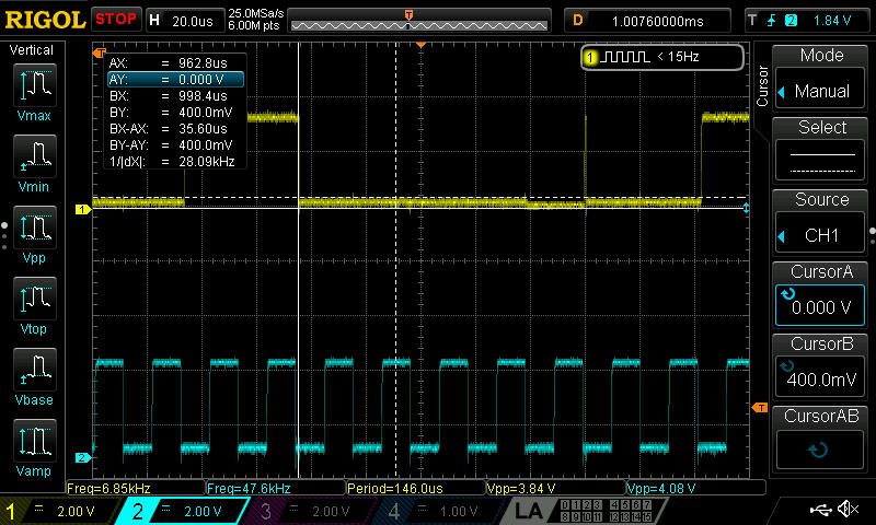
    page 1:

         0  1  2  3  4  5  6  7  8  9  a  b  c  d  e  f    0123456789abcdef

    00: 01 00 00 00 00 00 00 00 00 00 00 00 00 00 00 00    ?...............

    10: 00 00 00 00 00 00 00 00 00 00 00 00 00 00 00 04    ...............?

    20: 06 3e 00 40 7f 7f a5 7f 06 02 0c 00 20 86 00 bb    ?>.@???????. ?.?

    30: a8 20 00 00 00 00 00 00 00 00 00 00 00 00 00 00    ? ..............

    40: 00 00 00 00 00 00 00 00 00 00 00 00 00 00 00 00    ................

    50: 00 00 00 00 00 00 00 00 00 00 00 00 00 00 00 00    ................

    60: 00 00 00 00 00 00 00 00 00 00 00 00 00 00 00 00    ................

    70: 00 00 00 00 00 00 00 00 00 00 00 00 00 00 00 00    ................

    80: 00 00 00 00 00 00 00 00 00 00 00 00 00 00 00 00    ................

    90: 00 00 00 00 00 00 00 00 00 00 00 00 00 00 00 00    ................

    a0: 00 00 00 00 00 00 00 00 00 00 00 00 00 00 00 00    ................

    b0: 00 00 00 00 00 00 00 00 00 00 00 00 00 00 00 00    ................

    c0: 00 00 00 00 00 00 00 00 00 00 00 00 00 00 00 00    ................

    d0: 00 00 00 00 00 00 00 00 00 00 00 00 00 00 00 00    ................

    e0: 00 00 00 00 00 00 00 00 00 00 00 00 00 00 00 00    ................

    f0: 00 00 00 00 00 00 00 00 00 00 00 00 00 00 00 00    ................
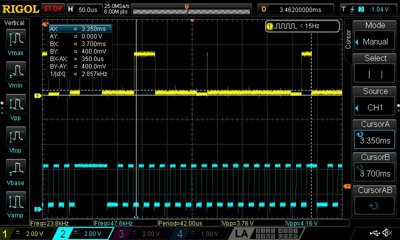
    state.vc4hdmi0 {
    	control.1 {
    		iface CARD
    		name 'HDMI Jack'
    		value false
    		comment {
    			access read
    			type BOOLEAN
    			count 1
    		}
    	}
    	control.2 {
    		iface PCM
    		name 'Playback Channel Map'
    		value.0 0
    		value.1 0
    		value.2 0
    		value.3 0
    		value.4 0
    		value.5 0
    		value.6 0
    		value.7 0
    		comment {
    			access 'read volatile'
    			type INTEGER
    			count 8
    			range '0 - 36'
    		}
    	}
    	control.3 {
    		iface PCM
    		name 'IEC958 Playback Mask'
    		value ffffffffffffffffffffffffffffffffffffffffffffffff0000000000000000000000000000000000000000000000000000000000000000000000000000000000000000000000000000000000000000000000000000000000000000000000000000000000000000000000000000000000000000000000000000000000000000000000000000000000000000000000000000000000000000000000000000000000000000000000000000000000000000
    		comment {
    			access read
    			type IEC958
    			count 1
    		}
    	}
    	control.4 {
    		iface PCM
    		name 'IEC958 Playback Default'
    		value '0400000100000000000000000000000000000000000000000000000000000000000000000000000000000000000000000000000000000000000000000000000000000000000000000000000000000000000000000000000000000000000000000000000000000000000000000000000000000000000000000000000000000000000000000000000000000000000000000000000000000000000000000000000000000000000000000000000000000000'
    		comment {
    			access 'read write'
    			type IEC958
    			count 1
    		}
    	}
    	control.5 {
    		iface PCM
    		name ELD
    		value '0000000000000000000000000000000000000000000000000000000000000000000000000000000000000000000000000000000000000000000000000000000000000000000000000000000000000000000000000000000000000000000000000000000000000000000000000000000000000000000000000000000000000000'
    		comment {
    			access 'read volatile'
    			type BYTES
    			count 128
    		}
    	}
    }
    state.vc4hdmi1 {
    	control.1 {
    		iface CARD
    		name 'HDMI Jack'
    		value true
    		comment {
    			access read
    			type BOOLEAN
    			count 1
    		}
    	}
    	control.2 {
    		iface PCM
    		name 'Playback Channel Map'
    		value.0 0
    		value.1 0
    		value.2 0
    		value.3 0
    		value.4 0
    		value.5 0
    		value.6 0
    		value.7 0
    		comment {
    			access 'read volatile'
    			type INTEGER
    			count 8
    			range '0 - 36'
    		}
    	}
    	control.3 {
    		iface PCM
    		name 'IEC958 Playback Mask'
    		value ffffffffffffffffffffffffffffffffffffffffffffffff0000000000000000000000000000000000000000000000000000000000000000000000000000000000000000000000000000000000000000000000000000000000000000000000000000000000000000000000000000000000000000000000000000000000000000000000000000000000000000000000000000000000000000000000000000000000000000000000000000000000000000
    		comment {
    			access read
    			type IEC958
    			count 1
    		}
    	}
    	control.4 {
    		iface PCM
    		name 'IEC958 Playback Default'
    		value '0400000100000000000000000000000000000000000000000000000000000000000000000000000000000000000000000000000000000000000000000000000000000000000000000000000000000000000000000000000000000000000000000000000000000000000000000000000000000000000000000000000000000000000000000000000000000000000000000000000000000000000000000000000000000000000000000000000000000000'
    		comment {
    			access 'read write'
    			type IEC958
    			count 1
    		}
    	}
    	control.5 {
    		iface PCM
    		name ELD
    		value '100007006b000000000000000000000010ac40d144454c4c2050323732334400000000000000000000000000000000000000000000000000000000000000000000000000000000000000000000000000000000000000000000000000000000000000000000000000000000000000000000000000000000000000000000000000'
    		comment {
    			access 'read volatile'
    			type BYTES
    			count 128
    		}
    	}
    }
    state.Headphones {
    	control.1 {
    		iface MIXER
    		name 'PCM Playback Volume'
    		value -1988
    		comment {
    			access 'read write'
    			type INTEGER
    			count 1
    			range '-10239 - 400'
    			dbmin -9999999
    			dbmax 400
    			dbvalue.0 -1988
    		}
    	}
    	control.2 {
    		iface MIXER
    		name 'PCM Playback Switch'
    		value true
    		comment {
    			access 'read write'
    			type BOOLEAN
    			count 1
    		}
    	}
    }
    state.TLV320AIC3120 {
    	control.1 {
    		iface MIXER
    		name 'ADC Fine Capture Volume'
    		value 4
    		comment {
    			access 'read write'
    			type INTEGER
    			count 1
    			range '0 - 4'
    			dbmin 0
    			dbmax 40
    			dbvalue.0 40
    		}
    	}
    	control.2 {
    		iface MIXER
    		name 'ADC Capture Switch'
    		value false
    		comment {
    			access 'read write'
    			type BOOLEAN
    			count 1
    		}
    	}
    	control.3 {
    		iface MIXER
    		name 'ADC Capture Volume'
    		value 24
    		comment {
    			access 'read write'
    			type INTEGER
    			count 1
    			range '0 - 64'
    			dbmin -2000
    			dbmax 1200
    			dbvalue.0 -800
    		}
    	}
    	control.4 {
    		iface MIXER
    		name 'Mic PGA Capture Volume'
    		value 0
    		comment {
    			access 'read write'
    			type INTEGER
    			count 1
    			range '0 - 119'
    			dbmin 0
    			dbmax 5950
    			dbvalue.0 0
    		}
    	}
    	control.5 {
    		iface MIXER
    		name 'Speaker Driver Playback Switch'
    		value true
    		comment {
    			access 'read write'
    			type BOOLEAN
    			count 1
    		}
    	}
    	control.6 {
    		iface MIXER
    		name 'Speaker Driver Playback Volume'
    		value 3
    		comment {
    			access 'read write'
    			type INTEGER
    			count 1
    			range '0 - 3'
    			dbmin 600
    			dbmax 2400
    			dbvalue.0 2400
    		}
    	}
    	control.7 {
    		iface MIXER
    		name 'Speaker Analog Playback Volume'
    		value 127
    		comment {
    			access 'read write'
    			type INTEGER
    			count 1
    			range '0 - 127'
    			dbmin -6350
    			dbmax 0
    			dbvalue.0 0
    		}
    	}
    	control.8 {
    		iface MIXER
    		name 'DAC Playback Volume'
    		value.0 175
    		value.1 175
    		comment {
    			access 'read write'
    			type INTEGER
    			count 2
    			range '0 - 175'
    			dbmin -6350
    			dbmax 2400
    			dbvalue.0 2400
    			dbvalue.1 2400
    		}
    	}
    	control.9 {
    		iface MIXER
    		name 'HP Driver Playback Switch'
    		value.0 true
    		value.1 false
    		comment {
    			access 'read write'
    			type BOOLEAN
    			count 2
    		}
    	}
    	control.10 {
    		iface MIXER
    		name 'HP Driver Playback Volume'
    		value.0 9
    		value.1 9
    		comment {
    			access 'read write'
    			type INTEGER
    			count 2
    			range '0 - 9'
    			dbmin 0
    			dbmax 900
    			dbvalue.0 900
    			dbvalue.1 900
    		}
    	}
    	control.11 {
    		iface MIXER
    		name 'HP Analog Playback Volume'
    		value.0 127
    		value.1 127
    		comment {
    			access 'read write'
    			type INTEGER
    			count 2
    			range '0 - 127'
    			dbmin -6350
    			dbmax 0
    			dbvalue.0 0
    			dbvalue.1 0
    		}
    	}
    	control.12 {
    		iface MIXER
    		name 'HP Output Driver Power-On time'
    		value '304ms'
    		comment {
    			access 'read write'
    			type ENUMERATED
    			count 1
    			item.0 '0us'
    			item.1 '15.3us'
    			item.2 '153us'
    			item.3 '1.53ms'
    			item.4 '15.3ms'
    			item.5 '76.2ms'
    			item.6 '153ms'
    			item.7 '304ms'
    			item.8 '610ms'
    			item.9 '1.22s'
    			item.10 '3.04s'
    			item.11 '6.1s'
    		}
    	}
    	control.13 {
    		iface MIXER
    		name 'HP Output Driver Ramp-up step'
    		value '3.9ms'
    		comment {
    			access 'read write'
    			type ENUMERATED
    			count 1
    			item.0 '0ms'
    			item.1 '0.98ms'
    			item.2 '1.95ms'
    			item.3 '3.9ms'
    		}
    	}
    	control.14 {
    		iface MIXER
    		name 'Volume Soft Stepping'
    		value fast
    		comment {
    			access 'read write'
    			type ENUMERATED
    			count 1
    			item.0 fast
    			item.1 slow
    			item.2 disabled
    		}
    	}
    	control.15 {
    		iface MIXER
    		name 'DAC Left Input'
    		value Off
    		comment {
    			access 'read write'
    			type ENUMERATED
    			count 1
    			item.0 Off
    			item.1 'Left Data'
    			item.2 'Right Data'
    			item.3 Mono
    		}
    	}
    	control.16 {
    		iface MIXER
    		name 'DAC Right Input'
    		value 'Right Data'
    		comment {
    			access 'read write'
    			type ENUMERATED
    			count 1
    			item.0 Off
    			item.1 'Right Data'
    			item.2 'Left Data'
    			item.3 Mono
    		}
    	}
    	control.17 {
    		iface MIXER
    		name 'HP Left Switch'
    		value true
    		comment {
    			access 'read write'
    			type BOOLEAN
    			count 1
    		}
    	}
    	control.18 {
    		iface MIXER
    		name 'HP Right Switch'
    		value true
    		comment {
    			access 'read write'
    			type BOOLEAN
    			count 1
    		}
    	}
    	control.19 {
    		iface MIXER
    		name 'MIC1LP P-Terminal'
    		value 'FFR 40 Ohm'
    		comment {
    			access 'read write'
    			type ENUMERATED
    			count 1
    			item.0 Off
    			item.1 'FFR 10 Ohm'
    			item.2 'FFR 20 Ohm'
    			item.3 'FFR 40 Ohm'
    		}
    	}
    	control.20 {
    		iface MIXER
    		name 'MIC1RP P-Terminal'
    		value 'FFR 20 Ohm'
    		comment {
    			access 'read write'
    			type ENUMERATED
    			count 1
    			item.0 Off
    			item.1 'FFR 10 Ohm'
    			item.2 'FFR 20 Ohm'
    			item.3 'FFR 40 Ohm'
    		}
    	}
    	control.21 {
    		iface MIXER
    		name 'MIC1LM P-Terminal'
    		value 'FFR 20 Ohm'
    		comment {
    			access 'read write'
    			type ENUMERATED
    			count 1
    			item.0 Off
    			item.1 'FFR 10 Ohm'
    			item.2 'FFR 20 Ohm'
    			item.3 'FFR 40 Ohm'
    		}
    	}
    	control.22 {
    		iface MIXER
    		name 'MIC1LM M-Terminal'
    		value 'FFR 10 Ohm'
    		comment {
    			access 'read write'
    			type ENUMERATED
    			count 1
    			item.0 Off
    			item.1 'FFR 10 Ohm'
    			item.2 'FFR 20 Ohm'
    			item.3 'FFR 40 Ohm'
    		}
    	}
    	control.23 {
    		iface MIXER
    		name 'Output Left From Left DAC'
    		value true
    		comment {
    			access 'read write'
    			type BOOLEAN
    			count 1
    		}
    	}
    	control.24 {
    		iface MIXER
    		name 'Output Left From MIC1LP'
    		value true
    		comment {
    			access 'read write'
    			type BOOLEAN
    			count 1
    		}
    	}
    	control.25 {
    		iface MIXER
    		name 'Output Left From MIC1RP'
    		value true
    		comment {
    			access 'read write'
    			type BOOLEAN
    			count 1
    		}
    	}
    	control.26 {
    		iface MIXER
    		name 'Output Right From Right DAC'
    		value true
    		comment {
    			access 'read write'
    			type BOOLEAN
    			count 1
    		}
    	}
    	control.27 {
    		iface MIXER
    		name 'Output Right From MIC1RP'
    		value true
    		comment {
    			access 'read write'
    			type BOOLEAN
    			count 1
    		}
    	}
    	control.28 {
    		iface MIXER
    		name 'Speaker Switch'
    		value true
    		comment {
    			access 'read write'
    			type BOOLEAN
    			count 1
    		}
    	}
    }
    state.sndrpihifiberry {
    	control {
    	}
    }
    state.sndrpirpidac {
    	control {
    	}
    }
    state.USBminiEVM {
    	control.1 {
    		iface PCM
    		name 'Playback Channel Map'
    		value.0 0
    		value.1 0
    		comment {
    			access 'read volatile'
    			type INTEGER
    			count 2
    			range '0 - 36'
    		}
    	}
    	control.2 {
    		iface PCM
    		name 'Capture Channel Map'
    		value.0 0
    		value.1 0
    		comment {
    			access 'read volatile'
    			type INTEGER
    			count 2
    			range '0 - 36'
    		}
    	}
    }
    state.Loopback {
    	control.1 {
    		iface PCM
    		name 'PCM Rate Shift 100000'
    		value 100000
    		comment {
    			access 'read write'
    			type INTEGER
    			count 1
    			range '80000 - 120000 (step 1)'
    		}
    	}
    	control.2 {
    		iface PCM
    		name 'PCM Notify'
    		value false
    		comment {
    			access 'read write'
    			type BOOLEAN
    			count 1
    		}
    	}
    	control.3 {
    		iface PCM
    		name 'PCM Slave Active'
    		value false
    		comment {
    			access read
    			type BOOLEAN
    			count 1
    		}
    	}
    	control.4 {
    		iface PCM
    		name 'PCM Slave Format'
    		value 2
    		comment {
    			access read
    			type INTEGER
    			count 1
    			range '0 - 52 (step 1)'
    		}
    	}
    	control.5 {
    		iface PCM
    		name 'PCM Slave Rate'
    		value 48000
    		comment {
    			access read
    			type INTEGER
    			count 1
    			range '0 - 192000 (step 1)'
    		}
    	}
    	control.6 {
    		iface PCM
    		name 'PCM Slave Channels'
    		value 2
    		comment {
    			access read
    			type INTEGER
    			count 1
    			range '1 - 1024 (step 1)'
    		}
    	}
    	control.7 {
    		iface PCM
    		name 'PCM Slave Access Mode'
    		value Interleaved
    		comment {
    			access read
    			type ENUMERATED
    			count 1
    			item.0 Interleaved
    			item.1 Non-interleaved
    		}
    	}
    	control.8 {
    		iface PCM
    		subdevice 1
    		name 'PCM Rate Shift 100000'
    		value 100000
    		comment {
    			access 'read write'
    			type INTEGER
    			count 1
    			range '80000 - 120000 (step 1)'
    		}
    	}
    	control.9 {
    		iface PCM
    		subdevice 1
    		name 'PCM Notify'
    		value false
    		comment {
    			access 'read write'
    			type BOOLEAN
    			count 1
    		}
    	}
    	control.10 {
    		iface PCM
    		subdevice 1
    		name 'PCM Slave Active'
    		value false
    		comment {
    			access read
    			type BOOLEAN
    			count 1
    		}
    	}
    	control.11 {
    		iface PCM
    		subdevice 1
    		name 'PCM Slave Format'
    		value 2
    		comment {
    			access read
    			type INTEGER
    			count 1
    			range '0 - 52 (step 1)'
    		}
    	}
    	control.12 {
    		iface PCM
    		subdevice 1
    		name 'PCM Slave Rate'
    		value 48000
    		comment {
    			access read
    			type INTEGER
    			count 1
    			range '0 - 192000 (step 1)'
    		}
    	}
    	control.13 {
    		iface PCM
    		subdevice 1
    		name 'PCM Slave Channels'
    		value 2
    		comment {
    			access read
    			type INTEGER
    			count 1
    			range '1 - 1024 (step 1)'
    		}
    	}
    	control.14 {
    		iface PCM
    		subdevice 1
    		name 'PCM Slave Access Mode'
    		value Interleaved
    		comment {
    			access read
    			type ENUMERATED
    			count 1
    			item.0 Interleaved
    			item.1 Non-interleaved
    		}
    	}
    	control.15 {
    		iface PCM
    		subdevice 2
    		name 'PCM Rate Shift 100000'
    		value 100000
    		comment {
    			access 'read write'
    			type INTEGER
    			count 1
    			range '80000 - 120000 (step 1)'
    		}
    	}
    	control.16 {
    		iface PCM
    		subdevice 2
    		name 'PCM Notify'
    		value false
    		comment {
    			access 'read write'
    			type BOOLEAN
    			count 1
    		}
    	}
    	control.17 {
    		iface PCM
    		subdevice 2
    		name 'PCM Slave Active'
    		value false
    		comment {
    			access read
    			type BOOLEAN
    			count 1
    		}
    	}
    	control.18 {
    		iface PCM
    		subdevice 2
    		name 'PCM Slave Format'
    		value 2
    		comment {
    			access read
    			type INTEGER
    			count 1
    			range '0 - 52 (step 1)'
    		}
    	}
    	control.19 {
    		iface PCM
    		subdevice 2
    		name 'PCM Slave Rate'
    		value 48000
    		comment {
    			access read
    			type INTEGER
    			count 1
    			range '0 - 192000 (step 1)'
    		}
    	}
    	control.20 {
    		iface PCM
    		subdevice 2
    		name 'PCM Slave Channels'
    		value 2
    		comment {
    			access read
    			type INTEGER
    			count 1
    			range '1 - 1024 (step 1)'
    		}
    	}
    	control.21 {
    		iface PCM
    		subdevice 2
    		name 'PCM Slave Access Mode'
    		value Interleaved
    		comment {
    			access read
    			type ENUMERATED
    			count 1
    			item.0 Interleaved
    			item.1 Non-interleaved
    		}
    	}
    	control.22 {
    		iface PCM
    		subdevice 3
    		name 'PCM Rate Shift 100000'
    		value 100000
    		comment {
    			access 'read write'
    			type INTEGER
    			count 1
    			range '80000 - 120000 (step 1)'
    		}
    	}
    	control.23 {
    		iface PCM
    		subdevice 3
    		name 'PCM Notify'
    		value false
    		comment {
    			access 'read write'
    			type BOOLEAN
    			count 1
    		}
    	}
    	control.24 {
    		iface PCM
    		subdevice 3
    		name 'PCM Slave Active'
    		value false
    		comment {
    			access read
    			type BOOLEAN
    			count 1
    		}
    	}
    	control.25 {
    		iface PCM
    		subdevice 3
    		name 'PCM Slave Format'
    		value 2
    		comment {
    			access read
    			type INTEGER
    			count 1
    			range '0 - 52 (step 1)'
    		}
    	}
    	control.26 {
    		iface PCM
    		subdevice 3
    		name 'PCM Slave Rate'
    		value 48000
    		comment {
    			access read
    			type INTEGER
    			count 1
    			range '0 - 192000 (step 1)'
    		}
    	}
    	control.27 {
    		iface PCM
    		subdevice 3
    		name 'PCM Slave Channels'
    		value 2
    		comment {
    			access read
    			type INTEGER
    			count 1
    			range '1 - 1024 (step 1)'
    		}
    	}
    	control.28 {
    		iface PCM
    		subdevice 3
    		name 'PCM Slave Access Mode'
    		value Interleaved
    		comment {
    			access read
    			type ENUMERATED
    			count 1
    			item.0 Interleaved
    			item.1 Non-interleaved
    		}
    	}
    	control.29 {
    		iface PCM
    		subdevice 4
    		name 'PCM Rate Shift 100000'
    		value 100000
    		comment {
    			access 'read write'
    			type INTEGER
    			count 1
    			range '80000 - 120000 (step 1)'
    		}
    	}
    	control.30 {
    		iface PCM
    		subdevice 4
    		name 'PCM Notify'
    		value false
    		comment {
    			access 'read write'
    			type BOOLEAN
    			count 1
    		}
    	}
    	control.31 {
    		iface PCM
    		subdevice 4
    		name 'PCM Slave Active'
    		value false
    		comment {
    			access read
    			type BOOLEAN
    			count 1
    		}
    	}
    	control.32 {
    		iface PCM
    		subdevice 4
    		name 'PCM Slave Format'
    		value 2
    		comment {
    			access read
    			type INTEGER
    			count 1
    			range '0 - 52 (step 1)'
    		}
    	}
    	control.33 {
    		iface PCM
    		subdevice 4
    		name 'PCM Slave Rate'
    		value 48000
    		comment {
    			access read
    			type INTEGER
    			count 1
    			range '0 - 192000 (step 1)'
    		}
    	}
    	control.34 {
    		iface PCM
    		subdevice 4
    		name 'PCM Slave Channels'
    		value 2
    		comment {
    			access read
    			type INTEGER
    			count 1
    			range '1 - 1024 (step 1)'
    		}
    	}
    	control.35 {
    		iface PCM
    		subdevice 4
    		name 'PCM Slave Access Mode'
    		value Interleaved
    		comment {
    			access read
    			type ENUMERATED
    			count 1
    			item.0 Interleaved
    			item.1 Non-interleaved
    		}
    	}
    	control.36 {
    		iface PCM
    		subdevice 5
    		name 'PCM Rate Shift 100000'
    		value 100000
    		comment {
    			access 'read write'
    			type INTEGER
    			count 1
    			range '80000 - 120000 (step 1)'
    		}
    	}
    	control.37 {
    		iface PCM
    		subdevice 5
    		name 'PCM Notify'
    		value false
    		comment {
    			access 'read write'
    			type BOOLEAN
    			count 1
    		}
    	}
    	control.38 {
    		iface PCM
    		subdevice 5
    		name 'PCM Slave Active'
    		value false
    		comment {
    			access read
    			type BOOLEAN
    			count 1
    		}
    	}
    	control.39 {
    		iface PCM
    		subdevice 5
    		name 'PCM Slave Format'
    		value 2
    		comment {
    			access read
    			type INTEGER
    			count 1
    			range '0 - 52 (step 1)'
    		}
    	}
    	control.40 {
    		iface PCM
    		subdevice 5
    		name 'PCM Slave Rate'
    		value 48000
    		comment {
    			access read
    			type INTEGER
    			count 1
    			range '0 - 192000 (step 1)'
    		}
    	}
    	control.41 {
    		iface PCM
    		subdevice 5
    		name 'PCM Slave Channels'
    		value 2
    		comment {
    			access read
    			type INTEGER
    			count 1
    			range '1 - 1024 (step 1)'
    		}
    	}
    	control.42 {
    		iface PCM
    		subdevice 5
    		name 'PCM Slave Access Mode'
    		value Interleaved
    		comment {
    			access read
    			type ENUMERATED
    			count 1
    			item.0 Interleaved
    			item.1 Non-interleaved
    		}
    	}
    	control.43 {
    		iface PCM
    		subdevice 6
    		name 'PCM Rate Shift 100000'
    		value 100000
    		comment {
    			access 'read write'
    			type INTEGER
    			count 1
    			range '80000 - 120000 (step 1)'
    		}
    	}
    	control.44 {
    		iface PCM
    		subdevice 6
    		name 'PCM Notify'
    		value false
    		comment {
    			access 'read write'
    			type BOOLEAN
    			count 1
    		}
    	}
    	control.45 {
    		iface PCM
    		subdevice 6
    		name 'PCM Slave Active'
    		value false
    		comment {
    			access read
    			type BOOLEAN
    			count 1
    		}
    	}
    	control.46 {
    		iface PCM
    		subdevice 6
    		name 'PCM Slave Format'
    		value 2
    		comment {
    			access read
    			type INTEGER
    			count 1
    			range '0 - 52 (step 1)'
    		}
    	}
    	control.47 {
    		iface PCM
    		subdevice 6
    		name 'PCM Slave Rate'
    		value 48000
    		comment {
    			access read
    			type INTEGER
    			count 1
    			range '0 - 192000 (step 1)'
    		}
    	}
    	control.48 {
    		iface PCM
    		subdevice 6
    		name 'PCM Slave Channels'
    		value 2
    		comment {
    			access read
    			type INTEGER
    			count 1
    			range '1 - 1024 (step 1)'
    		}
    	}
    	control.49 {
    		iface PCM
    		subdevice 6
    		name 'PCM Slave Access Mode'
    		value Interleaved
    		comment {
    			access read
    			type ENUMERATED
    			count 1
    			item.0 Interleaved
    			item.1 Non-interleaved
    		}
    	}
    	control.50 {
    		iface PCM
    		subdevice 7
    		name 'PCM Rate Shift 100000'
    		value 100000
    		comment {
    			access 'read write'
    			type INTEGER
    			count 1
    			range '80000 - 120000 (step 1)'
    		}
    	}
    	control.51 {
    		iface PCM
    		subdevice 7
    		name 'PCM Notify'
    		value false
    		comment {
    			access 'read write'
    			type BOOLEAN
    			count 1
    		}
    	}
    	control.52 {
    		iface PCM
    		subdevice 7
    		name 'PCM Slave Active'
    		value false
    		comment {
    			access read
    			type BOOLEAN
    			count 1
    		}
    	}
    	control.53 {
    		iface PCM
    		subdevice 7
    		name 'PCM Slave Format'
    		value 2
    		comment {
    			access read
    			type INTEGER
    			count 1
    			range '0 - 52 (step 1)'
    		}
    	}
    	control.54 {
    		iface PCM
    		subdevice 7
    		name 'PCM Slave Rate'
    		value 48000
    		comment {
    			access read
    			type INTEGER
    			count 1
    			range '0 - 192000 (step 1)'
    		}
    	}
    	control.55 {
    		iface PCM
    		subdevice 7
    		name 'PCM Slave Channels'
    		value 2
    		comment {
    			access read
    			type INTEGER
    			count 1
    			range '1 - 1024 (step 1)'
    		}
    	}
    	control.56 {
    		iface PCM
    		subdevice 7
    		name 'PCM Slave Access Mode'
    		value Interleaved
    		comment {
    			access read
    			type ENUMERATED
    			count 1
    			item.0 Interleaved
    			item.1 Non-interleaved
    		}
    	}
    	control.57 {
    		iface PCM
    		device 1
    		name 'PCM Rate Shift 100000'
    		value 100000
    		comment {
    			access 'read write'
    			type INTEGER
    			count 1
    			range '80000 - 120000 (step 1)'
    		}
    	}
    	control.58 {
    		iface PCM
    		device 1
    		name 'PCM Notify'
    		value false
    		comment {
    			access 'read write'
    			type BOOLEAN
    			count 1
    		}
    	}
    	control.59 {
    		iface PCM
    		device 1
    		name 'PCM Slave Active'
    		value false
    		comment {
    			access read
    			type BOOLEAN
    			count 1
    		}
    	}
    	control.60 {
    		iface PCM
    		device 1
    		name 'PCM Slave Format'
    		value 2
    		comment {
    			access read
    			type INTEGER
    			count 1
    			range '0 - 52 (step 1)'
    		}
    	}
    	control.61 {
    		iface PCM
    		device 1
    		name 'PCM Slave Rate'
    		value 48000
    		comment {
    			access read
    			type INTEGER
    			count 1
    			range '0 - 192000 (step 1)'
    		}
    	}
    	control.62 {
    		iface PCM
    		device 1
    		name 'PCM Slave Channels'
    		value 2
    		comment {
    			access read
    			type INTEGER
    			count 1
    			range '1 - 1024 (step 1)'
    		}
    	}
    	control.63 {
    		iface PCM
    		device 1
    		name 'PCM Slave Access Mode'
    		value Interleaved
    		comment {
    			access read
    			type ENUMERATED
    			count 1
    			item.0 Interleaved
    			item.1 Non-interleaved
    		}
    	}
    	control.64 {
    		iface PCM
    		device 1
    		subdevice 1
    		name 'PCM Rate Shift 100000'
    		value 100000
    		comment {
    			access 'read write'
    			type INTEGER
    			count 1
    			range '80000 - 120000 (step 1)'
    		}
    	}
    	control.65 {
    		iface PCM
    		device 1
    		subdevice 1
    		name 'PCM Notify'
    		value false
    		comment {
    			access 'read write'
    			type BOOLEAN
    			count 1
    		}
    	}
    	control.66 {
    		iface PCM
    		device 1
    		subdevice 1
    		name 'PCM Slave Active'
    		value false
    		comment {
    			access read
    			type BOOLEAN
    			count 1
    		}
    	}
    	control.67 {
    		iface PCM
    		device 1
    		subdevice 1
    		name 'PCM Slave Format'
    		value 2
    		comment {
    			access read
    			type INTEGER
    			count 1
    			range '0 - 52 (step 1)'
    		}
    	}
    	control.68 {
    		iface PCM
    		device 1
    		subdevice 1
    		name 'PCM Slave Rate'
    		value 48000
    		comment {
    			access read
    			type INTEGER
    			count 1
    			range '0 - 192000 (step 1)'
    		}
    	}
    	control.69 {
    		iface PCM
    		device 1
    		subdevice 1
    		name 'PCM Slave Channels'
    		value 2
    		comment {
    			access read
    			type INTEGER
    			count 1
    			range '1 - 1024 (step 1)'
    		}
    	}
    	control.70 {
    		iface PCM
    		device 1
    		subdevice 1
    		name 'PCM Slave Access Mode'
    		value Interleaved
    		comment {
    			access read
    			type ENUMERATED
    			count 1
    			item.0 Interleaved
    			item.1 Non-interleaved
    		}
    	}
    	control.71 {
    		iface PCM
    		device 1
    		subdevice 2
    		name 'PCM Rate Shift 100000'
    		value 100000
    		comment {
    			access 'read write'
    			type INTEGER
    			count 1
    			range '80000 - 120000 (step 1)'
    		}
    	}
    	control.72 {
    		iface PCM
    		device 1
    		subdevice 2
    		name 'PCM Notify'
    		value false
    		comment {
    			access 'read write'
    			type BOOLEAN
    			count 1
    		}
    	}
    	control.73 {
    		iface PCM
    		device 1
    		subdevice 2
    		name 'PCM Slave Active'
    		value false
    		comment {
    			access read
    			type BOOLEAN
    			count 1
    		}
    	}
    	control.74 {
    		iface PCM
    		device 1
    		subdevice 2
    		name 'PCM Slave Format'
    		value 2
    		comment {
    			access read
    			type INTEGER
    			count 1
    			range '0 - 52 (step 1)'
    		}
    	}
    	control.75 {
    		iface PCM
    		device 1
    		subdevice 2
    		name 'PCM Slave Rate'
    		value 48000
    		comment {
    			access read
    			type INTEGER
    			count 1
    			range '0 - 192000 (step 1)'
    		}
    	}
    	control.76 {
    		iface PCM
    		device 1
    		subdevice 2
    		name 'PCM Slave Channels'
    		value 2
    		comment {
    			access read
    			type INTEGER
    			count 1
    			range '1 - 1024 (step 1)'
    		}
    	}
    	control.77 {
    		iface PCM
    		device 1
    		subdevice 2
    		name 'PCM Slave Access Mode'
    		value Interleaved
    		comment {
    			access read
    			type ENUMERATED
    			count 1
    			item.0 Interleaved
    			item.1 Non-interleaved
    		}
    	}
    	control.78 {
    		iface PCM
    		device 1
    		subdevice 3
    		name 'PCM Rate Shift 100000'
    		value 100000
    		comment {
    			access 'read write'
    			type INTEGER
    			count 1
    			range '80000 - 120000 (step 1)'
    		}
    	}
    	control.79 {
    		iface PCM
    		device 1
    		subdevice 3
    		name 'PCM Notify'
    		value false
    		comment {
    			access 'read write'
    			type BOOLEAN
    			count 1
    		}
    	}
    	control.80 {
    		iface PCM
    		device 1
    		subdevice 3
    		name 'PCM Slave Active'
    		value false
    		comment {
    			access read
    			type BOOLEAN
    			count 1
    		}
    	}
    	control.81 {
    		iface PCM
    		device 1
    		subdevice 3
    		name 'PCM Slave Format'
    		value 2
    		comment {
    			access read
    			type INTEGER
    			count 1
    			range '0 - 52 (step 1)'
    		}
    	}
    	control.82 {
    		iface PCM
    		device 1
    		subdevice 3
    		name 'PCM Slave Rate'
    		value 48000
    		comment {
    			access read
    			type INTEGER
    			count 1
    			range '0 - 192000 (step 1)'
    		}
    	}
    	control.83 {
    		iface PCM
    		device 1
    		subdevice 3
    		name 'PCM Slave Channels'
    		value 2
    		comment {
    			access read
    			type INTEGER
    			count 1
    			range '1 - 1024 (step 1)'
    		}
    	}
    	control.84 {
    		iface PCM
    		device 1
    		subdevice 3
    		name 'PCM Slave Access Mode'
    		value Interleaved
    		comment {
    			access read
    			type ENUMERATED
    			count 1
    			item.0 Interleaved
    			item.1 Non-interleaved
    		}
    	}
    	control.85 {
    		iface PCM
    		device 1
    		subdevice 4
    		name 'PCM Rate Shift 100000'
    		value 100000
    		comment {
    			access 'read write'
    			type INTEGER
    			count 1
    			range '80000 - 120000 (step 1)'
    		}
    	}
    	control.86 {
    		iface PCM
    		device 1
    		subdevice 4
    		name 'PCM Notify'
    		value false
    		comment {
    			access 'read write'
    			type BOOLEAN
    			count 1
    		}
    	}
    	control.87 {
    		iface PCM
    		device 1
    		subdevice 4
    		name 'PCM Slave Active'
    		value false
    		comment {
    			access read
    			type BOOLEAN
    			count 1
    		}
    	}
    	control.88 {
    		iface PCM
    		device 1
    		subdevice 4
    		name 'PCM Slave Format'
    		value 2
    		comment {
    			access read
    			type INTEGER
    			count 1
    			range '0 - 52 (step 1)'
    		}
    	}
    	control.89 {
    		iface PCM
    		device 1
    		subdevice 4
    		name 'PCM Slave Rate'
    		value 48000
    		comment {
    			access read
    			type INTEGER
    			count 1
    			range '0 - 192000 (step 1)'
    		}
    	}
    	control.90 {
    		iface PCM
    		device 1
    		subdevice 4
    		name 'PCM Slave Channels'
    		value 2
    		comment {
    			access read
    			type INTEGER
    			count 1
    			range '1 - 1024 (step 1)'
    		}
    	}
    	control.91 {
    		iface PCM
    		device 1
    		subdevice 4
    		name 'PCM Slave Access Mode'
    		value Interleaved
    		comment {
    			access read
    			type ENUMERATED
    			count 1
    			item.0 Interleaved
    			item.1 Non-interleaved
    		}
    	}
    	control.92 {
    		iface PCM
    		device 1
    		subdevice 5
    		name 'PCM Rate Shift 100000'
    		value 100000
    		comment {
    			access 'read write'
    			type INTEGER
    			count 1
    			range '80000 - 120000 (step 1)'
    		}
    	}
    	control.93 {
    		iface PCM
    		device 1
    		subdevice 5
    		name 'PCM Notify'
    		value false
    		comment {
    			access 'read write'
    			type BOOLEAN
    			count 1
    		}
    	}
    	control.94 {
    		iface PCM
    		device 1
    		subdevice 5
    		name 'PCM Slave Active'
    		value false
    		comment {
    			access read
    			type BOOLEAN
    			count 1
    		}
    	}
    	control.95 {
    		iface PCM
    		device 1
    		subdevice 5
    		name 'PCM Slave Format'
    		value 2
    		comment {
    			access read
    			type INTEGER
    			count 1
    			range '0 - 52 (step 1)'
    		}
    	}
    	control.96 {
    		iface PCM
    		device 1
    		subdevice 5
    		name 'PCM Slave Rate'
    		value 48000
    		comment {
    			access read
    			type INTEGER
    			count 1
    			range '0 - 192000 (step 1)'
    		}
    	}
    	control.97 {
    		iface PCM
    		device 1
    		subdevice 5
    		name 'PCM Slave Channels'
    		value 2
    		comment {
    			access read
    			type INTEGER
    			count 1
    			range '1 - 1024 (step 1)'
    		}
    	}
    	control.98 {
    		iface PCM
    		device 1
    		subdevice 5
    		name 'PCM Slave Access Mode'
    		value Interleaved
    		comment {
    			access read
    			type ENUMERATED
    			count 1
    			item.0 Interleaved
    			item.1 Non-interleaved
    		}
    	}
    	control.99 {
    		iface PCM
    		device 1
    		subdevice 6
    		name 'PCM Rate Shift 100000'
    		value 100000
    		comment {
    			access 'read write'
    			type INTEGER
    			count 1
    			range '80000 - 120000 (step 1)'
    		}
    	}
    	control.100 {
    		iface PCM
    		device 1
    		subdevice 6
    		name 'PCM Notify'
    		value false
    		comment {
    			access 'read write'
    			type BOOLEAN
    			count 1
    		}
    	}
    	control.101 {
    		iface PCM
    		device 1
    		subdevice 6
    		name 'PCM Slave Active'
    		value false
    		comment {
    			access read
    			type BOOLEAN
    			count 1
    		}
    	}
    	control.102 {
    		iface PCM
    		device 1
    		subdevice 6
    		name 'PCM Slave Format'
    		value 2
    		comment {
    			access read
    			type INTEGER
    			count 1
    			range '0 - 52 (step 1)'
    		}
    	}
    	control.103 {
    		iface PCM
    		device 1
    		subdevice 6
    		name 'PCM Slave Rate'
    		value 48000
    		comment {
    			access read
    			type INTEGER
    			count 1
    			range '0 - 192000 (step 1)'
    		}
    	}
    	control.104 {
    		iface PCM
    		device 1
    		subdevice 6
    		name 'PCM Slave Channels'
    		value 2
    		comment {
    			access read
    			type INTEGER
    			count 1
    			range '1 - 1024 (step 1)'
    		}
    	}
    	control.105 {
    		iface PCM
    		device 1
    		subdevice 6
    		name 'PCM Slave Access Mode'
    		value Interleaved
    		comment {
    			access read
    			type ENUMERATED
    			count 1
    			item.0 Interleaved
    			item.1 Non-interleaved
    		}
    	}
    	control.106 {
    		iface PCM
    		device 1
    		subdevice 7
    		name 'PCM Rate Shift 100000'
    		value 100000
    		comment {
    			access 'read write'
    			type INTEGER
    			count 1
    			range '80000 - 120000 (step 1)'
    		}
    	}
    	control.107 {
    		iface PCM
    		device 1
    		subdevice 7
    		name 'PCM Notify'
    		value false
    		comment {
    			access 'read write'
    			type BOOLEAN
    			count 1
    		}
    	}
    	control.108 {
    		iface PCM
    		device 1
    		subdevice 7
    		name 'PCM Slave Active'
    		value false
    		comment {
    			access read
    			type BOOLEAN
    			count 1
    		}
    	}
    	control.109 {
    		iface PCM
    		device 1
    		subdevice 7
    		name 'PCM Slave Format'
    		value 2
    		comment {
    			access read
    			type INTEGER
    			count 1
    			range '0 - 52 (step 1)'
    		}
    	}
    	control.110 {
    		iface PCM
    		device 1
    		subdevice 7
    		name 'PCM Slave Rate'
    		value 48000
    		comment {
    			access read
    			type INTEGER
    			count 1
    			range '0 - 192000 (step 1)'
    		}
    	}
    	control.111 {
    		iface PCM
    		device 1
    		subdevice 7
    		name 'PCM Slave Channels'
    		value 2
    		comment {
    			access read
    			type INTEGER
    			count 1
    			range '1 - 1024 (step 1)'
    		}
    	}
    	control.112 {
    		iface PCM
    		device 1
    		subdevice 7
    		name 'PCM Slave Access Mode'
    		value Interleaved
    		comment {
    			access read
    			type ENUMERATED
    			count 1
    			item.0 Interleaved
    			item.1 Non-interleaved
    		}
    	}
    	control.113 {
    		iface MIXER
    		name 'PCM Playback Volume'
    		value.0 136
    		value.1 136
    		comment {
    			access 'read write user'
    			type INTEGER
    			count 2
    			range '0 - 255'
    			tlv '0000000100000008ffffec1400000014'
    			dbmin -5100
    			dbmax 0
    			dbvalue.0 -2380
    			dbvalue.1 -2380
    		}
    	}
    }
    

  • Mir,

    Additionally, attached is my overlay file.

    Thanks,

    Caleb

    /dts-v1/;
    /plugin/;
    
    / {
        compatible = "brcm,bcm2835";
    
        /* Fragment 0: Define power regulators FIRST */
        fragment@0 {
            target-path = "/";
            __overlay__ {
                /* 3.3V regulator for analog/digital IO */
                vdd_3v3_reg: regulator_3v3 {
                    compatible = "regulator-fixed";
                    regulator-name = "vdd-3v3";
                    regulator-min-microvolt = <3300000>;
                    regulator-max-microvolt = <3300000>;
                    regulator-always-on;
                    regulator-boot-on;
                };
    
                /* 1.8V regulator for digital core - CRITICAL */
                vdd_1v8_reg: regulator_1v8 {
                    compatible = "regulator-fixed";
                    regulator-name = "vdd-1v8";
                    regulator-min-microvolt = <1800000>;
                    regulator-max-microvolt = <1800000>;
                    regulator-always-on;
                    regulator-boot-on;
                };
            };
        };
    
        fragment@1 {
            target = <&i2s>;
            __overlay__ {
                status = "okay";
            };
        };
    
    //    fragment@1 {
    //        target = <&gpio>; //"/soc/gpio@7e200000"; //<&gpio>;
    //        __overlay__ {
    //            gpclk0_pins: gpclk0_pins {
    //                brcm,pins = <4>;  // GPIO4 is GPCLK0
    //                brcm,function = <4>;  // ALT0 function
    //                brcm,pull = <0>;  // No pull-up/down
    //            };
    //        };
    //    };
    
    //    fragment@2 {
    //        target = <&clocks>; //"/soc/clock@7ef00000"; //<&clocks>;
    //        __overlay__ {
    //            gpclk0: gpclk0 {
    //                compatible = "fixed-clock";
    //                #clock-cells = <0>;
    //                clock-frequency = <11289600>;  // 11.2896 MHz
    //                clock-output-names = "gpclk0";
    //            };
    //        };
    //    };
    
        fragment@2 {
            target = <&i2c1>; //"/soc/i2c@7e804000"; //<&i2c1>;
            __overlay__ {
                #address-cells = <1>;
                #size-cells = <0>;
    
                tlv320: tlv320aic3120@18 {
                    compatible = "ti,tlv320aic3120";
                    reg = <0x18>;
                    #sound-dai-cells = <0>;
                    clocks = <&dummy_clock>; //<&gpclk0>; //<&dummy_clock>;
                    clock-names = "mclk";
    
                    /* Power supply rails - CORRECT voltages */
                    /* All 3.3V rails */
                    HPVDD-supply = <&vdd_3v3_reg>;    /* Headphone driver power */
                    SPLVDD-supply = <&vdd_3v3_reg>;   /* Speaker driver power */
                    SPRVDD-supply = <&vdd_3v3_reg>; 
                    AVDD-supply = <&vdd_3v3_reg>;     /* Analog power */
                    IOVDD-supply = <&vdd_3v3_reg>;    /* Digital IO power */
                    
                    /* 1.8V rail - CRITICAL */
                    DVDD-supply = <&vdd_1v8_reg>;     /* Digital core power */
                    
                    /* Optional: Reset GPIO */
                    reset-gpios = <&gpio 17 0>;  /* GPIO17, active low */
                    
                    /* MICBIAS configuration */
                    ai31xx-micbias-vg = <2>;  /* 0=2.0V, 1=2.5V, 2=AVDD */
                };
            };
        };
    
        fragment@3 {
            target-path = "/";
            __overlay__ {
                dummy_clock: dummy_clock {
                    compatible = "fixed-clock";
                    #clock-cells = <0>;
                    clock-frequency = <11289600>; // 12.288 MHz
                    clock-output-names = "dummy-mclk";
                };
                sound {
                    compatible = "simple-audio-card";
                    simple-audio-card,name = "TLV320AIC3120";
                    simple-audio-card,format = "i2s";
                    simple-audio-card,bitclock-master = <&cpu_dai>;
                    simple-audio-card,frame-master = <&cpu_dai>;
                    simple-audio-card,channels-min = <2>;
                    simple-audio-card,channels-max = <2>;
    
                    cpu_dai: simple-audio-card,cpu {
                        sound-dai = <&i2s>;
                    };
    
                    codec_dai: simple-audio-card,codec {
                        sound-dai = <&tlv320>;
                    };
                };
            };
        };
    };


  • Mir,

    I should add that the comment in my overlay file next to the micbias configuration is wrong, it is actually 1=2.0V, 2=2.5V, 3=AVDD. I also tried setting 0x2e directly as 0x0a but that did not seem to fix my issue.

    Thanks,

    Caleb

  • Mir,

    After some testing, it seems that what may be happening is that the codec is not recognizing that there is any microphone connected to it. Is there any way to tell if the codec recognizes that there is a microphone connected to it? 

    I reached this conclusion after measuring R16 while writing 0x0a directly to 0x2e and seeing that the voltage was in fact changing from 0V to 2.5V, and yet I continued to have the same issue with a silent wavefile. In addition, by viewing the stats of the wavefile with sox I saw that the bit-depth was listed as 0/0 despite running arecord with signed 16 bit little endian. I also verified that the microphone was working by connecting it to my laptop and seeing that it could detect my voice. 

    Please get back to me on what you think my next steps should be.

    Thank you,

    Caleb

  • Hi Caleb,

    I was writing my response but glad you updated here. When you are recording, the driver will change the registers to match what it thinks you need, based on the connections in the dts file. So, if it does not recognize the micbias config, or does not have the inputs selected, it will not "connect" the microphone to the ADC. I noticed in the earlier register dump you gave, it was not during a recording (or something is up with the clocks?) but the inputs path has changed since the last time. We see 0x30 is set to 0xa8 and 0x31 is set to 0x20 (in page 1). This would be this path:

    I assume you just have 1 mic connected? If it is single ended, you should configure it for just that mic in on the P terminal and VCOM on the M terminal. 

    Best,
    Mir

  • Mir,

    The i2cdumps I sent were supposed to be from during a recording, however because I cannot run the i2cdump command while the driver is attached to the codec what I need to do is unbind the driver while the arecord command is running and then run i2cdump. This may mean that I did not successfully get the i2cdump of the registers while arecord is actually running as running the unbind command will kill arecord. But as far as I know this is my only option for showing the registers. 

    Why is the path listed there incorrect? Should I only have one of MIC1RP or MIC1LP set? Should MIC1LM P-Channel not be set and only M-Channel?

    Thanks,

    Caleb

  • Mir,

    I tried running it with just MIC1LM M-Channel set and then iterating through setting the other three to no success. 

    Thanks,

    Caleb

  • Mir,

    I have tried iterating through every combination of MIC1LP, MIC1RP, MIC1LM P-Channel, and MIC1LM M-Channel, to no success. From the registers before can you tell if anything else is set up incorrectly? Is there something I need to do with VCOM? I figured the codec handled it internally. Please let me know the next steps I should take when you can.

    Thanks,

    Caleb

  • Mir,

    To make it completely clear, the issue is that the microphone is not picking up anything, not even noise.

    Thanks for understanding,

    Caleb

  • If you can share a schematic and the pinout of your microphone this will help me understand. Maybe a picture of your setup with the EVM? The issue is likely with the connection. If you were able to see microphone signal coming out on a scope the mic should be fine, just the way you are connecting to the EVM is the issue.

    -Mir

  • Mir,

    Unfortunately I do not have any details on the microphone, I just quickly ordered a microphone with a 3.5mm audio jack online, this is the link to the Amazon listing: https://www.amazon.com/Replacement-Afterglow-Turtle-Headset-Smartphone/dp/B086YSHZ81?dib=eyJ2IjoiMSJ9.FX7rtvLNUaF2FsqAMm45Gd5xcumnMzaZ8E9kl-Y_ZdrRp2wLpDBVglz801NXhNc72xsLO3BUeVmNP47n4UM9SWtmgWYy6C-qVBn9mdvw7XZVso4rwz8cclwPhWrhIEMMVgD0c2qbmZZfnGhIYQkMyLTaOagRlm97nF-JpyxbSc-4lOhj8e2SWkGbN9vMsQrcoltdaks-1VKrW-MuM6_vHYPPRt5BcIzaH3YYZA0-1gcL3zUCsluQX8CzZt-ofg6UwlUWh5UCAISYY5-e8lqYgE7WyGmH2jg9iPIMCr9Qy68.caz4fX1LfsqQexnl3wRKnDOOtAuSNi4aNNZa0z64LNI&dib_tag=se&keywords=3.5mm+microphone&qid=1761148346&sr=8-30#averageCustomerReviewsAnchor 

    The pinout between the Raspberry Pi 4 and the evm is what I already sent, it has not changed beyond that I attached the microphone to the J2-MIC IN female audio jack. 

    For seeing the microphone signal coming out on a scope, how would you recommend I do that? I tried probing C18/C19 for AC Voltage and could not tell if what I was looking at was just noise as it did not change while I was running arecord or not.

    Thanks,

    Caleb

  • Mir,

    I have some questions about some of values in some of the registers.

    When doing an i2cdump I can see that page 0 0x24 has value 0x80 meaning that the ADC PGA applied gain ≠ programmed gain, and page 0 0x27 has value 0x08 meaning that Delta-Sigma Mono ADC Overflow has occurred.

    Page 0 register 0x43 also seems to signify that there is no headset detected as the values are just 0x00?

    And lastly, for page 0 register 0x51, what should the value be to get input from the microphone at J2? Currently it is set to 0x00 in my register dump. 

    Do any of these values indicate anything incorrect? I am also included the i2cdumps here.

    Thanks,

    Caleb

    pi@raspberrypi:~ $ i2cdump -y 1 0x18

    No size specified (using byte-data access)

         0  1  2  3  4  5  6  7  8  9  a  b  c  d  e  f    0123456789abcdef

    00: 01 00 00 00 00 00 00 00 00 00 00 00 00 00 00 00    ?...............

    10: 00 00 00 00 00 00 00 00 00 00 00 00 00 00 00 04    ...............?

    20: 06 3e 00 40 7f 7f a4 7f 06 02 0c 00 20 86 0a ba    ?>.@???????. ???

    30: a8 20 00 00 00 00 00 00 00 00 00 00 00 00 00 00    ? ..............

    40: 00 00 00 00 00 00 00 00 00 00 00 00 00 00 00 00    ................

    50: 00 00 00 00 00 00 00 00 00 00 00 00 00 00 00 00    ................

    60: 00 00 00 00 00 00 00 00 00 00 00 00 00 00 00 00    ................

    70: 00 00 00 00 00 00 00 00 00 00 00 00 00 00 00 00    ................

    80: 00 00 00 00 00 00 00 00 00 00 00 00 00 00 00 00    ................

    90: 00 00 00 00 00 00 00 00 00 00 00 00 00 00 00 00    ................

    a0: 00 00 00 00 00 00 00 00 00 00 00 00 00 00 00 00    ................

    b0: 00 00 00 00 00 00 00 00 00 00 00 00 00 00 00 00    ................

    c0: 00 00 00 00 00 00 00 00 00 00 00 00 00 00 00 00    ................

    d0: 00 00 00 00 00 00 00 00 00 00 00 00 00 00 00 00    ................

    e0: 00 00 00 00 00 00 00 00 00 00 00 00 00 00 00 00    ................

    f0: 00 00 00 00 00 00 00 00 00 00 00 00 00 00 00 00    ................
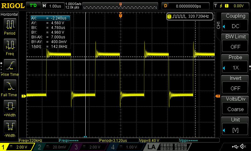
    pi@raspberrypi:~ $ i2cset -y 1 0x18 0x00 0x00

    pi@raspberrypi:~ $ i2cdump -y 1 0x18

    No size specified (using byte-data access)

         0  1  2  3  4  5  6  7  8  9  a  b  c  d  e  f    0123456789abcdef

    00: 00 00 01 66 00 11 04 00 00 00 00 01 01 00 80 80    ..?f.??....??.??

    10: 08 00 01 01 80 80 04 00 00 00 01 00 00 00 01 00    ?.?????...?...?.

    20: 00 00 00 00 80 00 11 08 00 00 00 00 00 00 00 00    ....?.??........

    30: 00 00 00 02 32 12 03 02 02 11 10 00 01 04 00 30    ...?2??????.??.0

    40: 0c 09 09 00 6f 38 00 00 00 00 00 ee 10 d8 7e e3    ???.o8.....???~?

    50: 00 00 80 00 00 00 00 00 7f 00 00 00 00 00 00 00    ..?.....?.......

    60: 00 00 00 00 00 00 00 00 00 00 00 00 00 00 00 00    ................

    70: 00 00 00 00 00 00 00 00 00 00 00 00 00 00 00 00    ................

    80: 00 00 00 00 00 00 00 00 00 00 00 00 00 00 00 00    ................

    90: 00 00 00 00 00 00 00 00 00 00 00 00 00 00 00 00    ................

    a0: 00 00 00 00 00 00 00 00 00 00 00 00 00 00 00 00    ................

    b0: 00 00 00 00 00 00 00 00 00 00 00 00 00 00 00 00    ................

    c0: 00 00 00 00 00 00 00 00 00 00 00 00 00 00 00 00    ................

    d0: 00 00 00 00 00 00 00 00 00 00 00 00 00 00 00 00    ................

    e0: 00 00 00 00 00 00 00 00 00 00 00 00 00 00 00 00    ................

    f0: 00 00 00 00 00 00 00 00 00 00 00 00 00 00 00 00    ................
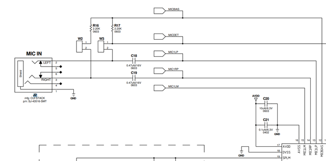
  • Mir,

    I forced i2cdumps from while arecord was running and noticed that on page 0 register 0x52, the value is still 0x80 meaning the ADC channel is muted according to the datasheet even while arecord was running. Could this potentially be the cause of my issue? The i2cdumps are below.

    Thanks,

    Caleb

         0  1  2  3  4  5  6  7  8  9  a  b  c  d  e  f    0123456789abcdef

    00: 00 00 01 66 00 91 04 00 00 00 00 81 81 00 80 80    ..?f.??....??.??

    10: 08 00 81 81 80 80 04 00 00 00 01 00 00 00 81 00    ?.?????...?...?.

    20: 00 00 00 00 c0 00 11 08 00 00 00 00 00 00 00 00    ....?.??........

    30: 00 00 00 02 32 12 03 02 02 11 10 00 01 04 00 30    ...?2??????.??.0

    40: 0c 09 09 00 6f 38 00 00 00 00 00 ee 10 d8 7e e3    ???.o8.....???~?

    50: 00 80 80 00 00 00 00 00 7f 00 00 00 00 00 00 00    .??.....?.......

    60: 00 00 00 00 00 00 00 00 00 00 00 00 00 00 00 00    ................

    70: 00 00 00 00 00 00 00 00 00 00 00 00 00 00 00 00    ................

    80: 00 00 00 00 00 00 00 00 00 00 00 00 00 00 00 00    ................

    90: 00 00 00 00 00 00 00 00 00 00 00 00 00 00 00 00    ................

    a0: 00 00 00 00 00 00 00 00 00 00 00 00 00 00 00 00    ................

    b0: 00 00 00 00 00 00 00 00 00 00 00 00 00 00 00 00    ................

    c0: 00 00 00 00 00 00 00 00 00 00 00 00 00 00 00 00    ................

    d0: 00 00 00 00 00 00 00 00 00 00 00 00 00 00 00 00    ................

    e0: 00 00 00 00 00 00 00 00 00 00 00 00 00 00 00 00    ................

    f0: 00 00 00 00 00 00 00 00 00 00 00 00 00 00 00 00    ................

         0  1  2  3  4  5  6  7  8  9  a  b  c  d  e  f    0123456789abcdef

    00: 01 00 00 00 00 00 00 00 00 00 00 00 00 00 00 00    ?...............

    10: 00 00 00 00 00 00 00 00 00 00 00 00 00 00 00 04    ...............?

    20: 06 3e 00 40 7f 7f a4 7f 06 02 0c 00 20 86 0a 3a    ?>.@???????. ??:

    30: a8 20 00 00 00 00 00 00 00 00 00 00 00 00 00 00    ? ..............

    40: 00 00 00 00 00 00 00 00 00 00 00 00 00 00 00 00    ................

    50: 00 00 00 00 00 00 00 00 00 00 00 00 00 00 00 00    ................

    60: 00 00 00 00 00 00 00 00 00 00 00 00 00 00 00 00    ................

    70: 00 00 00 00 00 00 00 00 00 00 00 00 00 00 00 00    ................

    80: 00 00 00 00 00 00 00 00 00 00 00 00 00 00 00 00    ................

    90: 00 00 00 00 00 00 00 00 00 00 00 00 00 00 00 00    ................

    a0: 00 00 00 00 00 00 00 00 00 00 00 00 00 00 00 00    ................

    b0: 00 00 00 00 00 00 00 00 00 00 00 00 00 00 00 00    ................

    c0: 00 00 00 00 00 00 00 00 00 00 00 00 00 00 00 00    ................

    d0: 00 00 00 00 00 00 00 00 00 00 00 00 00 00 00 00    ................

    e0: 00 00 00 00 00 00 00 00 00 00 00 00 00 00 00 00    ................

    f0: 00 00 00 00 00 00 00 00 00 00 00 00 00 00 00 00    ................

  • Mir,

    This removed my issue of having the wavefile created be all zeros but it still seems to not pick up anything recorded and .when played out of the speaker I just hear static/noise

    Thanks,

    Caleb

  • Hi Caleb,

    If the ADC is muted, yes it will not pick up anything. We expect register 0x51 bit D7 to be 1 for ADC channel powered up, and D3 to be 0 for analog microphone and NOT digital microphone. I see the ADC is muted with register 0x52, this is controlled with the driver will something called the "ADC Capture Switch".  

    I see that the ADC has had the overflow flag for the last 2 register dumps at least. This may mean that your input signal is too high voltage. If you know the voltage swing of your input that would be good to check. There is a chance we can decrease the input voltage making it to the PGA by increasing the input impedance.

    About register 0x43, headset detection is disabled so it would not show either way. 

    Best,
    Mir

  • Mir,

    What exactly is the input signal you are referring to? Is it the signal from the microphone? Because that bit was set to 1 even when I did not have a microphone connected to the codec.

    How would I increase the input impedance?

    Thanks,

    Caleb

  • Mir,

    I switched to using my computer to play a video which I had wired to go into J2 with the codec set as headphones and with arecord on the Pi I got a wavefile that when played has the audio from the video but deeper and slowed, which seems like it may be a sample rate issue. I am still looking into it now but I was wondering if you had any ideas about it?

    Thanks,

    Caleb

  • I am talking about the mic signal, but that flag being high is a little strange. I am not sure if it is a sticky flag, what happens when you read it twice in a row? And can you verify that the mic input pin isn't over .707Vrms (2Vpp centered around micbias).

    Make sure your sample rate of the video is the same as set on the Pi. It may be a 44.1k vs 48k issue.

    -Mir

  • Mir,

    Apologies for the delayed response, I was away. After copying the wavefile over to another computer and playing it out it did not sound slowed. This would seem to indicate that the reason it sounded slowed was due to how the speakers are set somehow. Do you have any ideas on what could be causing this? Also, reading 0x27 set the flag to 0.

    Thanks,

    Caleb

  • Hi,

    If, for example, the recording was at 48k but the device was at 44.1k, then playing it back at 44.1k without resampling the file will make it sound slower/lower pitch. 

    This is likely a quirk of the RPi and the way you are playing these files not necessarily how the codec itself is configured. The codec will adjust to whatever the MCU is providing for the clocks. Typically an operating system that is not Linux will have this resampling built in. I believe you can set the playback sample rate for an audio file on Linux with aplay -r 48000, or whatever sample rate you intend to play back the file. aplay documentation is here: https://linux.die.net/man/1/aplay

    Good to know that the flag is sticky. If you want to check for overflow, you will want to read it first to verify that it is 0 and then check again during or after playback/recording a file.

    Best,
    Mir