Hi Team,
There is a thermal issue of TAS5825M on the customer board. Please check the attachments below and let me know your recommended solutions.
Regards,
Hi Team,
There is a thermal issue of TAS5825M on the customer board. Please check the attachments below and let me know your recommended solutions.
Regards,
Hi Jeffrey,
Can you please check the fault registers to see if any faults occured during this thermal issue?
Also is this issue occuring only with no audio input?
1. Thermal issue.
The device will always output a PWM in play mode. Unless the device is set to Hi-z or sleep/deepsleep mode then you will see the outputs switching.
2. PCB
I will provide more feedback here once I review the layout.
3. Inductor current rating
This depends on how much output power you're pushing and loading conditions. The inductor should be chosen so the LC filter does not saturate to near zero inductance wtihin normal operating conditions. The inductor rating should be above the peak current in your application to avoid saturation, preferably with some margin like 20%.
4. Thermal Vias
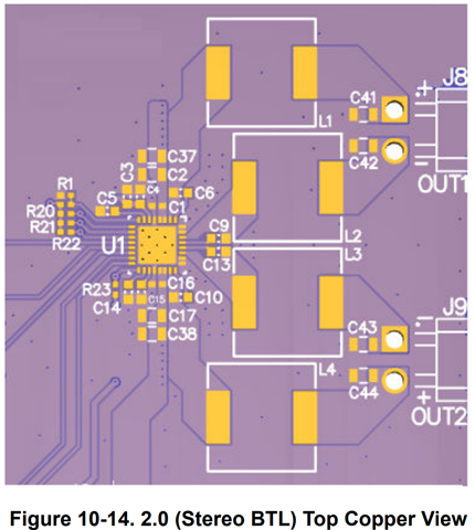
There should be more vias here from the thermal pad to GND, this will hlep to transfer heat to the ground plane. Here's a snippet from the layout guidelines:

Regards,
Sebastian
Hi Jeffrey,
Can you please provide the layout in another format or in a pdf? I'm not able to open these gerbers.
Regards,
Sebastian
Hi Sebastian,
Let me check your request with customer and update it. Thank you for your support.
Regards,
Hi Sebastian,
I got a updated gerber file that there is no problem. Please check it again.
Regards,
Hi Jeffrey,
Can they please send this in a format that is not gerbers or at least snippets of the layout in a PDF? I'm not able to open these gerbers.
Regards,
Sebastian
Hi Sebastian,
I got the pdf file for layout review from customer. Please check the file and additional questions attached below.
Can you please check the fault registers to see if any faults occured during this thermal issue?
Also is this issue occuring only with no audio input?
Any faults are not occurred during this thermal issue, and this issue is occurring with audio input and without audio input.
Regard,
Hi Jeffrey,
So just to confirm the functionality of the device is fine they just want to improve the thermals? Does this issue also occur when the amp is shutdown? Is this on just one board or multiple?
Additional questions
1. What is the recommended ESR value of ceramic capacitors for PVDD?
There is no blanket recommendation in terms of ESR for decoupling capacitors for PVDD, however generally lower ESR is desirable. This app note goes into further detail: https://www.ti.com/lit/an/slyt199/slyt199.pdf
2. It says that the bootstrap capacitor uses 0.47uF in the datasheet. Are there any points to effect on the thermal of TAS5825M by bootstrap capacitor value?
Capacitors will generate heat when charging/discharging. Minimizing the ESR will help minimize heat generation.
3. The snubber circuit is used on the customer’s board. Are there any points to effect on that with or without it?
The snubber circuit will dissipate some power and add to heat generation on the board. Unless this is needed for EMI purposes, perhaps they can test without this to see if the thermal issue improves.
4. The capacitor of LC filter uses a ceramic capacitor. Are there any points to effect on that when using a film capacitor instead of ceramic one?
In terms of thermal generation, the lower the ESR the less power dissipated. Generally a ceramic capacitor will have lower ESR than a film capacitor.
Layout questions
Reviewing the layout in this format is difficult, if you could provide a .brd or another format where I can identify the pins/nets that would be helpful. I can't provide feedback on trace width if I have no scale to reference.
Regards,
Sebastian
Hi Sebastian,
So just to confirm the functionality of the device is fine they just want to improve the thermals? The functionality of the device is no problem, they just want to improve the thermal.
Does this issue also occur when the amp is shutdown? They didn't check it.
Is this on just one board or multiple? There are 5 devices(TAS5825M) on one board.
Also, please check my private message for layout review.
Regards,
Hi Jeffrey,
My question was whether the same thermals are seen on other PCBs not just one?
Also, can they not use a pad up device? These can be used with a heatsink and will have much better thermal performance.
Thermal considerations are hard to generalize since there many factors that can influence the performance.
With no audio input the output will be switching at a 50% duty cycle, and the switching losses of the amplifier will be dominant. With a 24V supply this will this will generate alot of heat. Even if testing at room temp of 25C, the heat generated will be much higher due to power losses (mainly switching with no input).
I suggest comparing the EVM with the customer board. The EVM uses many more thermal vias to connect the thermal pad to GND.
Increasing copper thickness will also help with heat dissipation.
These app notes should be helpful: Thermal design considerations for TAS5805M Class-D audio amplifier
PowerPAD Thermally Enhanced Package (Rev. H)
Regards,
Sebastian
Hi Sebastian,
My question was whether the same thermals are seen on other PCBs not just one? Yes, this issue is occurred on other PCBs.
Also, can they not use a pad up device? They use it with a heatsink, but they are trying to do the best thermal performance without a heatsink.
Thank you for your support.
Regards,
Hi Jeffrey,
I received your email but these are still in a gerber format. I cannot properly review this layer by layer, my previous commentary/app note suggestions should be a good starting point for improving thermals.
Regards,
Sebastian