


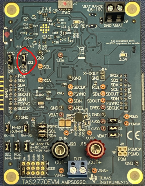
The TAS2770EVM that I recently purchased does not seem to match the board images in figure 5 of the Users Guide, or the schematic. For example J23 (circled in Red on top side picture below) is not in the picture or schematic or the BOM at the end of the Users Guide.
Also U25 and U27 are not in the schematic (perhaps Ref Des changed?), see circled from back side below:

These components are of interest to me because I want to run the device in 1.8V mode (my SOM has 1.8V only IO) and I'd like to know how the I2C 1.8V configuration jumper at J23 works.


