TAS2563: TAS2563 configuration

Part Number: TAS2563


Hi,

We are using two TAS2563 IC interface spakers in our product.


I have belwo questions to understand more:

  1. When our device is shutdown only VBAT power is present and VDD & IOVDD is off. In this case, the register configurations are still present ?
  2. We have dual core processor. One core run with RTOS and other core run with LINUX. So which place is idle to keep headers and configure the speaker via i2c?
  3. What are the mandatory headers we need to configure on these files? what is the difference between each file? what is the sequence we need to follow.
    image.png
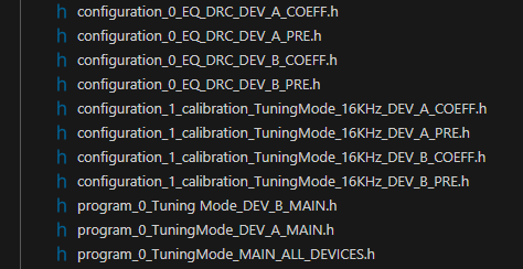
  4. What are the headers(generated from PPC3) do we need to configure on cold boot(complete power off and on) and warm boot( only VBAT present)?  
  5. When we have two ICs on same bus then can we configure the both the ICs with global address for all regsiters? Most likely we use mono.
  6. what is the main power on /off sequence to be followed for the speaker?
  7. We need two audio profiles(1: talk, 2: siren), By default we configure with speaker with talk.Suppose we need to play siren then what are the headers files required to configure the spaker?
  8. If we wanted to read the temp of IC. what steps to be followed.
  9. what is the main use of IRQZ signal?Is it mandatory to use this?
  10. which register to be configured to control the volume?

Thanks,

Chandra


  • Hi Chandra,

    I'm adding comments on each item below:

    1. The memory is cleared when VDD goes low. In this case the configuration will not remain present.
    2. Both baremetal and linux drivers are available for TAS2563, so you can use whichever is more convenient for your system.
    3. The required files are:
      1. configuration_0_EQ_DRC_DEV_A_COEFF.h
      2. configuration_0_EQ_DRC_DEV_B_COEFF.h
      3. program_0_TuningMode_DEV_A_MAIN.h
      4. program_0_TuningMode_DEV_B_MAIN.h
      5. program_0_TuningMode_MAIN_ALL_DEVICES.h
    4. In this case both cold and warm boot seem to power down VDD supply, so you'll need to configure the device after either boot sequence.
    5. Yes, for common settings you can use the global address. If there is any difference in configuration between the devices then those specific registers should be set using the dedicated address for each one.
    6. There is no sequence required for the power rails. During power down it is recommended to first set the device into SW shutdown (register 0x02) and then power down the voltage supply.
    7. You can use PPC3 to set 2 snapshots in the same PPC3 file. When configuration files are generated, select both snapshots and you'll get a set of COEFF files for each snapshot (for example, "configuration_0_..." and "configuration_1_..."). The "program_0_..." file is shared for both profiles.
    8. You can read the SAR TMP conversion data from register 0x2c. You have to subtract 93 from the read value, the result is in degrees C.
    9. IRQz is used to notify the host processor that any unmasked flag has been triggered. Not mandatory.
    10. When using TAS2563 in Tuning mode, it is best to use the digital volume control from the Tuning and Audio Processing features. This is a 32-bit coefficient located in Page 7 Registers 0x10 through 0x13.
      If there is a way to adjust the input signal amplitude using some mixer or similar tool, it would be preferred as the device configuration can remain the same.

    Hope this helps clarifying the device operation, let me know if there are follow up questions.

    Best regards,
    -Ivan Salazar
    Applications Engineer

  • Hi Ivan,

    thanks for the comments.

    please check my follow-up questions:

    1.If we do not want to configure the TAS2563 on every warm boot, then what are the changes we need to do in schematic. Because we cannot configure more than 5000 registers on every boot up. What is the current consumption of the IC if it's in shutdown mode.

    2.what is the difference in below files (main and main all):

    1. program_0_TuningMode_DEV_A_MAIN.h
    2. program_0_TuningMode_DEV_B_MAIN.h
    3. program_0_TuningMode_MAIN_ALL_DEVICES.h

    3.After power ON, do we need to reset the registers before configuring the registers? Is there any configuration order we need to follow?

    4.Before reading the temp then do we need to generate the active clock?

    5. For volume control we are thinking to set the digital gain constant and adjust the volume in audio codec file.Is there any issue in here?

    6.Is there any help you can provide to integrate the driver either in linux or rtos.

    7.Does calibration is not required along with other configuration files?

    Thanks,

    Chandra

  • Hi Chandra,

    1. I would suggest finding a way to keep VDD power on, this way the memory is not cleared. In SW shutdown the consumption from VDD is ~10uA and from VBAT is ~1uA (included in data sheet "Typical Current Consumption" table).
    2. MAIN_ALL_DEVICES file includes settings that are shared across device A and device B. If you're using a single device, you'll have a single program_0_... file.
    3. SW reset after power on is best practice to bring up the device from known state. No specific order to follow, just keep the command for Active mode in register 0x02 as the last one to avoid unwanted transients at the output during configuration.
    4. Yes, clock must be present, and the device should be in Active mode in order to read die temp.
    5. This should be OK.
    6. We can follow up on this question through email/meeting.
    7. Calibration (FCT) is implemented during final production; there are different ways to implement it depending on the driver being used. I think we can also follow up through email/meeting, it is best for our software experts to comment on these last two questions.

    Best regards,
    -Ivan Salazar
    Applications Engineer