This thread has been locked.

If you have a related question, please click the "Ask a related question" button in the top right corner. The newly created question will be automatically linked to this question.

TAS5805M: The mute issue for TAS5805M

Part Number: TAS5805M
Other Parts Discussed in Thread: TAS5805

Hi,

Please kindly review our schematic diagram, TAS5805M will be muted when the power is 23W, and we read the register that the 0X72 is change to 00 when it is mute, the schematic diagram and register map please refer to below:

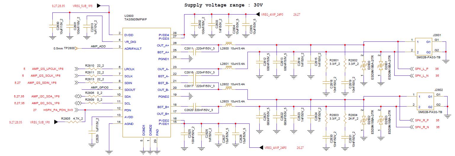
 2ed081e625a72892116bc9b13c53d67c.jpg

TAS5805MPWP.jpg

  • Hi ZhangLiang,

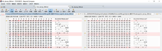
    the register shows that it meet OTSD. 

    please check the thermal design whether there is good thermal conditions. the chip uses the thermal pad located under the chip, and use PCB board for the heat dissipation. make sure there is enough hold on the thermal pad.

    Br,

    Wenbin 

    .

  • Hi Wenbin,

    You mean it is only the heat dissipation issue and we don't need to modify our schematic? thanks.

  • Hi ZhangLiang,

    the SCH seems fine. and I think the shutdown happens after long time playback under high output power. in this case, it's only the thermal issue.

    Br,

    Wenbin

  • Hi Wenbin,

    We have below issue for our testing result:

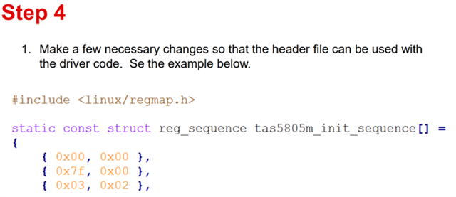
    1. How can the offline debug file regmap.h exported by TAS5805 using PPC3 be integrated into the version-compatible driver to work together?

    And How to Generate a Header File fro TAS5805M in PPC3? 

    2. Are the parameter debugging options for TI limited to offline mode and real-time mode on the development board? Is it impossible to use TI tools for real-time debugging of the entire machine? Can we only write the regmap.h file into the software version using software methods, or is there any other quick method to replace it for standalone verification?
    3. Do we need to export *.h files to set up for each state, or just read out the register differences and preset them in the software version, and then call the parameter settings for the corresponding state based on the upper-level state?
    4. When using the AP525 sine wave sweep signal source for electrical signal frequency response testing, the volume control quickly mutes at low frequencies in Volume 204, but it can complete playback in Volume 205 (under fan cooling conditions).
    State Control Play verifies three modes (with fan cooling), reproduces volume 204 quick mute in BD mode, can play through in Hybrid mode, and can play through in 1spw mode
    In fanless mode, only the 1spw mode can complete the entire frequency sweep test when playing at Volume 204.
     
     
  • Hi ZhangLiang,

    regarding the item 1~3, it related to SW Driver, I will forward it.

    regarding item4, this is because of the thermal. BD will generate a little more thermal than the other two mode. so I think it is very margin in your design.

    I believe you can run the full sweep in a lower volume for the three modes.

     you can check 0x72 register, the value 01 means it meet OTSD(over temperature shutdown).

    Br,

    Wenbin

  • Q1: As far as I know, ppc3 can generate the header file. What you do is copy the array inside the new header file, and paste it into the code.

    Q2: You can have the online tuning. The simple way is to connect the i2c from the device to the EVM board.

    Q3: What's the mean of each state. In our code, the setting only load during init. If the TAS5805m is not hardware shutdown, the code won't load the setting any longer.

  • HI  Shenghao,

    Thanks for your kindly support.

    And now, we want to know the specific registers required for the three modes, as well as those needed for tuning and debugging

    How to incorporate register parameters in 5805? thanks.
  • Hi Guy,

    The specific registers you mentioned are the dsp menory mapped units, not the simple registers.

    P20 at TAS5805M, TAS5806M, and TAS5806MD Process Flows (Rev. A), we do not recommmended our customer to set them by their own.

  • Hi Shenghao,

    Can you check out our schematic diagram that we need to prototype now, thanks.

  • Sorry, I'm the software guy. You may as well raise a new thread dedicated to the schematic diagram.

  • Hi Liang,

    The schematic is ok in overall, only recommendation is to use the 10uH output inductor with higher saturation current like 4.5A or above, to avoid large ripples and THD degradation in the output when Isat is only 3.4A. Thanks. 

  • Hi Peter & Shenghao,

    Many thanks for your kindly support. we will modify our inductor based on your commnet.

  • Hi Liang,

    You are welcome, hopefully the issue is resolved and the project goes well.