This thread has been locked.

If you have a related question, please click the "Ask a related question" button in the top right corner. The newly created question will be automatically linked to this question.

PGA2311: Design guidelines for audio based PCB

Part Number: PGA2311
Other Parts Discussed in Thread: TLV320AIC3104, , TPA6120A2

I’m working on a mixed-signal audio board and would really appreciate some feedback regarding my layout and grounding strategy.

On the left side of the board, I have:

  • TLV320AIC3104 (audio codec)

  • PGA2311 (digitally controlled volume)

  • LDO regulators (3.3V and 1.8V)

  • TXU level shifter for SPI communication

  • MCU feeding I2S to the codec and SPI to the PGA (through the level shifter)

On the right side, I have:

  • TPA6120A2 headphone amplifier

  • Analog output routing and output connectors

I have physically separated the digital/control section and the analog amplifier section. AGND and DGND are isolated in layout and connected using a star grounding approach at a single point.

For testing flexibility, I have placed jumpers between the PGA output and the TPA input.


My Questions:

  1. With this placement (digital on left, analog on right), is there a chance of noise coupling from:

    • I2S lines?

    • SPI signals through the level shifter?

    • The jumpers between PGA and TPA?

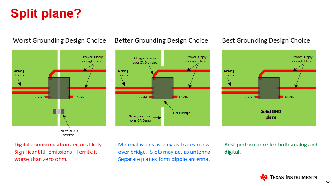
  2. Is star grounding still recommended in this type of audio design, or would a continuous ground plane be better?

I’m mainly concerned about maintaining low noise performance in the headphone amplifier stage.

Any guidance or layout suggestions would be very helpful.

  • Hello,

    With this placement (digital on left, analog on right), is there a chance of noise coupling from:

    • I2S lines?

    • SPI signals through the level shifter?

    • The jumpers between PGA and TPA?

    I2S is low risk if the traces are kept short and routed over a solid ground plane. The SPI  through the level shifter is ok if the level shifter is placed near the digital section and proper decoupling capacitors are used. For the PGA to TPA jumpers this would be the most sensitive since it is low level analog. Keep the traces short and avoid routing near digital signals/sections. Consider using 0 ohm resistor or solder bridge across pads for the lowest noise. 

    Is star grounding still recommended in this type of audio design, or would a continuous ground plane be better?

    Some engineers will create a separate analog and digital ground plane in order to avoid corrupting the sensitive analog with crosstalk noise from the communications digital.  Frequently, the two GND planes are connected together at one point near the ADC with a zero ohm resistor, inductor, or a ferrite.  This approach was widely promoted as a good idea 30 years ago.  It turns out that this is generally not a good approach.  Signals that traverse the split will have large RF emissions and frequently have poor analog performance.  Using an inductor or ferrite can generate large transient voltages when switching currents pass from digital to analog ground and this can cause data errors and may even damage the device.  For engineers who really want to use a split a better approach is the use a ground bridge as shown in the center drawing.   The ground bridge needs to be wide enough to allow any digital traces to pass over the bridge and not over a split in the ground.  The best grounding choice is to simply use a solid plane and to make sure to keep the physical distance of the digital and other noisy signals away from the analog.  The process of physically segmenting different signal types to different sections of the PCB is called floor planning, and a good floor plan is a much better approach to minimize coupling of digital into analog then a split plane. 

    For best layout practices please see our video training series on PCB design for good EMC. The link will take you to the Precision labs series: Analog-to-digital converters (ADCs). Please look at the topics for  PCB design for good EMC. 

    https://www.ti.com/video/series/precision-labs/ti-precision-labs-analog-to-digital-converters-adcs.html

    I hope this information is helpful. 

    Best Regards, 

    Chris Featherstone