This thread has been locked.

If you have a related question, please click the "Ask a related question" button in the top right corner. The newly created question will be automatically linked to this question.

TAS2781: PVDDL not being generated internally

Part Number: TAS2781

Dear Ladies and Gents,

we're having some troubles in getting the TAS2781 running properly on our own PCB design. We can communictate with the TAS2781 over I2C and configure it. Unfortunately the PVDDL is not being generated internally.
We've tested the settings etc. with the eval board and everything is working fine there.

The TAS2781 is only being activated when the I2S clock / signal is present. 

Could you please check if you see a mistake in our schematics?
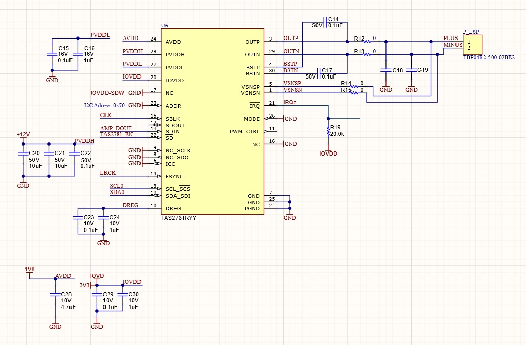
TAS2781.jpg

Thanks in advance for your appreciated help.

Best regards,

Laurent


  • Hi Laurent, 

    The schematic looks fine i don't see any issues.

    the most common issue for why PVDDL is not generated internally is because too much capacitance is on PVDDL.  but 1uF + 0.1uF is OK

    Also, for the purpose of this initial testing can you please use the default PWR_MODE2 script from the datasheet section "10.4 Initial Device Configuration - PWR_MODE2"

    There are a few reasons why the device may not power up

    - I2C config is wrong

    -I2S Clocks are invalid

    - one or more of the supplies is not present

    - PVDDH is too low and the LDO cannot regulate properly. if you have provided 12 V PVDDH then it should be OK . 

    Can you please also read the registers 0x49 - 0x51 on book 0 page 0? this will give all of the latched interrupts. this may tell us if the device is not powering up due to a clock error, or UVLO or something else

    Regards,

    Arthur