A related question is a question created from another question. When the related question is created, it will be automatically linked to the original question.
If you have a related question, please click the "Ask a related question" button in the top right corner. The newly created question will be automatically linked to this question.
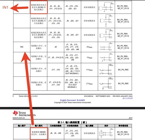
The following table is the content on page 8 of the DEMO board manual. Looking at this table,
1. Is it true that tad5212 material only supports electret MIC in IN1 and IN2 analog MIC in IN2? Is this just an example or a fixed configuration?
2. For the electret single-ended AC coupling mode, there is a pull-up bias in front of the isolation capacitor. Is this resistor 10k? Still needs to be adjusted? Also, is it necessary to reserve a pull-up resistor at the back end of the DC-blocking capacitor, that is, at the input terminal of the chip?
3. For the electret single-ended AC coupling mode, what is the bias voltage of the signal? Do I need to configure it myself? If so, what bias voltage should a general analog headset be configured with?
4. For the board-level analog MIC AC coupling method, as shown in the following figure, only 10uF capacitors need to be connected in series with positive and negative terminals, and there is no need to pull them up and down, right? If it is a single-ended input, the front end of the IN2M DC blocking capacitor doesn't need to be grounded either, right?
First, keep in mind that the TAD5212 does not have an ADC path. Analog inputs are only supported in the analog bypass path.
1. Is it true that tad5212 material only supports electret MIC in IN1 and IN2 analog MIC in IN2? Is this just an example or a fixed configuration?
This is just an example based on how the EVM is connected. There are actually no mics connected on the TAD5212 board. This is only available on the TAC5212 and TAA5212 board.
2. For the electret single-ended AC coupling mode, there is a pull-up bias in front of the isolation capacitor. Is this resistor 10k? Still needs to be adjusted? Also, is it necessary to reserve a pull-up resistor at the back end of the DC-blocking capacitor, that is, at the input terminal of the chip?
On the EVM, this resistor is 1.1k. It is not necessary to have pull-up on the chip side, as this device has an internal pull-up for quick-charge of the coupling capacitor.
3. For the electret single-ended AC coupling mode, what is the bias voltage of the signal? Do I need to configure it myself? If so, what bias voltage should a general analog headset be configured with?
The bias voltage from MICBIAS is configurable in register 0x4D. The default is 2.75V. This should be suitable for most applications, but you can read more about headset detection here: https://www.ti.com/lit/an/slaaeg7/slaaeg7.pdf
4. For the board-level analog MIC AC coupling method, as shown in the following figure, only 10uF capacitors need to be connected in series with positive and negative terminals, and there is no need to pull them up and down, right? If it is a single-ended input, the front end of the IN2M DC blocking capacitor doesn't need to be grounded either, right?
The front end of the AC coupling capacitor should be grounded in single-ended mode.