This thread has been locked.

If you have a related question, please click the "Ask a related question" button in the top right corner. The newly created question will be automatically linked to this question.

TAC5212: request design support

Part Number: TAC5212

We plan to use the TAC5212 in our custom communication system (5-100 kHz, low signal level, noisy environment).

I have done an initial quick test with the TAC5212-EVM, but clearly this is a device with many options and adjustments. So we would like some expert support to give us a quick first push towards actual design/implementation in our system, to discuss application pitfalls, for software / device configuration and for hardware signal design (input and output) based on our specific requirements and situation.

For your practical information, we are located in the Netherlands. Looking forward to hear from you and discuss the options.

With best regards,

Harry Kroonen

+31 6 3978 2467

  • Hi Harry,

    Please let me know your design requirements and I can provide support.

    Best,

    Garret

  • Hi Garret, in a nutshell:

    We have a (20 years old) system build with discrete amplifiers on TX + RX and audio DA / AD ic's, with modulated signal between 5-20 kHz.

    Now looking into upgrade / redesign and found the TAC5212 with impressive more features. Of most interest are higher datarate / sampling speed and input sensitivity / adjustable gain (and filtering always nice).  

    I am no audio engineer, and I purchased the EVK and fiddled around for a day with the PurePath software and got pretty much utterly confused about most of the options.

    Basic functions (generating a digital sound from laptop and sending that to analog output / seeing that on oscilloscope) and (function generator on analog input seeing a digital bitstream changing) I managed okay.

    But more advanced actions with controlling gain, mixing signals and filtering created various results, from somewhat logical to total failure and confusion :-). (It has been a few weeks busy with other things, so for exact details I need to give it another try and properly document my actions).

    So as first step, it would be nice to have some examples / tutorial / walkthrough demonstration. I watched your video introduction but found not much more assistance for a newby.

    As a starting point, the basic application use case / requirements:

    1. Use as (DA) converter, with signal input digital from microcontroller.

    2. Use as (AA) converter, with analog input signal and TAC5212 inserting adjustable gain.

    3. Use as AD converter, with signal in 5-100 kHz range with adjustable gain to handle signal level from 1 Volt down to (microvolts / as low as possible).

    Best regards,

    Harry

  • Hi Harry,

    1. Use as (DA) converter, with signal input digital from microcontroller.

    The EVM user guide has several examples for common configurations starting on page 31. For this application you can use the " Target Mode Playback to Differential LINEOUT with Primary Audio Serial Interface (PASI)" script:

    2. Use as (AA) converter, with analog input signal and TAC5212 inserting adjustable gain.

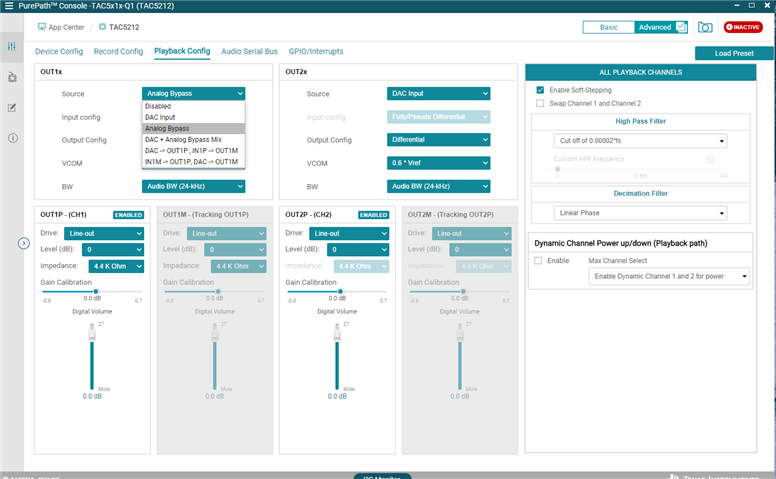
    This is achieved with the Analog Bypass feature, selectable on the Playback Config window:

    Gain can be inserted with the Digital Volume slider shown here.

    3. Use as AD converter, with signal in 5-100 kHz range with adjustable gain to handle signal level from 1 Volt down to (microvolts / as low as possible).

    This is a bit more difficult, as since this is an audio codec, it is only spec'ed for up to a 20kHz input signal, but to set up a Record path, you can use one of the scripts from the user guide.

    Let me know if you have any more questions.

    Best,

    Garret

  • Hi Garret,

    I just tested the Analog Bypass mode.

    Testsignal input sinusoid, 5 kHz, 100 mVolt pk-pk.

    Output differential on OUT1P / OUT2P

    Level (dB) selector 0 dB -> output measured ok / 100 mV pk-pk

    Selecting -12 / -6 dB / +6dB level adjusts the output as expected.

    ( I think the Digital Volume slider does nothing in this configuration?) 

    But +12 dB creates a spiky mess (pulses at 20 microsec) , and +18 / +24 dB seem to switch off output.

    I tried this with various Drive/impedance settings and also different loads on the output, but nothing seems to make a difference. 

    Is this expected behaviour, or am I messing something up?

    Regards,

    Harry

  • Hi Harry,

    This is expected, +18 and +24dB are not actually available configurations in the register map:

    I am not sure why they still appear in PPC3.

    Best,

    Garret