This thread has been locked.

If you have a related question, please click the "Ask a related question" button in the top right corner. The newly created question will be automatically linked to this question.

TLV320AIC3107: Output level higher than AGC target gain setting

Part Number: TLV320AIC3107

Hi,

The issue concerns the AGC function of the TLV320AIC3107.
The output level is higher than the configured target gain value.

What could be the cause of this behavior?

Based on the AGC parameter settings, the expected output level should be 141 mVrms.
However, the actual measured output is 294 mVrms, which is approximately 6 dB higher.

A difference of around 1 dB could be considered acceptable error, but 6 dB seems too large.

Input conditions and results:
1.Input signal: 133 mVrms
2.Output signal: 294 mVrms
3.Expected output signal: 141 mVrms
  (Full scale = 0.707 Vrms, therefore -14 dB corresponds to 0.141 Vrms)

AGC parameters:
1.Target Gain: -14 dB
2.Max Gain Allowed: 59.5 dB

Other conditions:
1.The same result was obtained with both a 1 kHz sine wave input and pseudo-audio signals.
2.Signal path: LINE1LP (single-ended) input → I2S loopback → LEFT_LOP output
3.All internal gain settings are configured to 0 dB
4.Verified using the evaluation board
5.The output was measured with a high-impedance load.

Kind regards

  • Hi,

    6dB higher seems like it could be a single ended vs differential mismatch. Are you giving is 133mVrms on one pin single ended or is it differential? Are you reading 294mVrms on just left LOP or left LOP/LOM differential? Can you share the register configuration you are using for this?

    Best,
    Mir

  • Hi,

    The input signal was measured as a single-ended signal using one signal line; it was not measured as a differential signal.
    The input was applied to J6 pin 1 (LINE1LP), and SW1 on the evaluation board was set to "SE".
    The output signal was measured from the single-ended LEFT_LOP signal; it was not measured as a differential signal.
    I will send the register settings.

    Kind regards

    reg.csv

  • Hi,

    These register settings are a dump? Or how are you sending the registers, so I can test on an EVM. I think the doubling may be a quirk with single ended mode, or potentially a mismatch with your I2S/TDM settings. If you change the target gain, does it stay doubled from what you expect on the output? 

    -Mir

  • Hi,

    The register data is a dump read directly from the IC.

    The registers are written via I2C using the evaluation board application.

    Even when changing the target gain setting, the output level is approximately twice the expected value.
    The results are shown below.

    Target gain: -8 dB / Output: 616 mVrms / Expected: 281 mVrms
    Target gain: -14 dB / Output: 285 mVrms / Expected: 141 mVrms
    Target gain: -20 dB / Output: 143 mVrms / Expected: 71 mVrms

    Kind regards

  • Hi,

    Sorry, give me another day to test it out on my end. However I was looking through the register dump, how are you doing the I2S loopback? Is it a register or are you using a cable between them? 

    Best,
    Mir

  • Hi,

    Understood regarding the test procedure.
    The I2S loopback is implemented by connecting J14 pin 7 and J14 pin 9 on the evaluation board (USB-MODEVM Interface) with a jumper wire.

    Kind regards

  • Hi,

    If you turn off AGC and instead just look at the passthrough, do you see the same input voltage or twice the input voltage at the output? This should help you determine the cause of this. If you see twice the input voltage, then you can decrease the AGC target by 6dB and the output will be what you expect.

    Best,
    Mir

  • Hi,

    I verified the behavior with AGC disabled.
    Since the output level is close to the input level, I believe the issue is related to the AGC operation.

    PGA Gain: 0 dB / Input: 138 mVrms / Output: 158 mVrms
    PGA Gain: 6 dB / Input: 138 mVrms / Output: 324 mVrms

    PGA Gain: 0 dB / Input: 44 mVrms / Output: 50 mVrms
    PGA Gain: 6 dB / Input: 44 mVrms / Output: 102 mVrms
    PGA Gain: 12 dB / Input: 44 mVrms / Output: 209 mVrms
    PGA Gain: 18 dB / Input: 44 mVrms / Output: 423 mVrms

    Since this device is intended for audio applications, I wonder whether the AGC behavior is designed differently from RF AGC.

    In other words, instead of precisely matching the configured target level,
    could it be designed with some margin for audio applications,
    where gain adjustment stops once the signal reaches a certain acceptable range?

    Kind regards

  • Hi,

    Those signal levels seem reasonable for the PGA gain, there may be some small error in the gain measurement internal to the AGC, and the AGC is limited to steps of 0.5dB of the PGA gain to adjust. The AGC target level stratification combined with the PGA granularity is the "margin" for the gain to stop. Can you send the RF AGC you are referring to so I can understand the difference? 

    Best,
    Mir

  • Hi,

    I may have caused some confusion.

    I do not have any specific RF AGC data.
    I mentioned RF AGC only for comparison, with the following intent.

    AGC is commonly used in many RF applications, such as RSSI control.
    In those applications, AGC is often expected to achieve relatively accurate target levels, typically within around 1 dB tolerance, depending on system requirements.

    In contrast, the IC currently under discussion shows more than 5 dB deviation from the target level.
    A 5 dB deviation might be considered problematic for a typical RF AGC IC.

    However, since this IC is designed for audio applications, I was wondering whether it may intentionally use a different design philosophy.

    For example, since speech intelligibility is important in audio applications,
    could there be some algorithm or behavior that intentionally biases the output level slightly higher to ensure the audio is heard more clearly?

    Kind regards

  • Hi,

    Ok, no problem, I understand. In the AIC3107, the input level detection algorithm is done with "absolute average" aka the average of the absolute value of the signal. So, already this is not the most accurate level detection system, and is not the same as the rms level. The absolute average will vary based on the type of input signal. I did some research into this to check the amount of error, and here are some useful sources: https://electrical-information.com/the-difference-of-average-and-rms/ https://electronics.stackexchange.com/questions/40341/why-v-rms-instead-of-v-average

    So, the amount of RMS error for a sine wave is around 11%, which checks out for these input levels to output with the PGA gain at 0dB. With higher PGA gain, measurement error can scale, which I believe is what you were seeing with your measurements.

    In general, the AGC is meant for keeping voice signals close to the same "target" level, although this target may be not at the same measurement that we would expect due to the input signal measurement error between rms and abs avg. However, it is working as expected with these measurements you observed. The other parameters of the AGC are time-based, since the user may be moving around with respect to the microphone, so we want to adjust the PGA gain to match close to the input signal as it was before the user moved. The time parameters can vary based on the adjustments that you would expect the user to be making and the input level range you expect. 

    Overall, I would suggest adjusting the AGC "expected level" to ~10% higher than you would want (not in dBs but in absolute level percentage), if you expect the input signal to be closest to a sine wave. When it is a speech signal, there is more uncertainty of the percent error of RMS to abs avg. However the algorithm is working as expected to keep the input signal close to constant volume.

    Best,
    Mir

  • Hi,

    Thank you for the explanation.

    However, the difference between RMS and average value appears to be only around 1 dB, so I do not believe this alone explains the approximately 5 dB discrepancy.

    I understand that this may be one contributing factor, but I suspect there may be additional reasons as well.
    Could you clarify what those might be?

    For example, is it possible that the definition of the target gain is different from my understanding?

    I calculated the expected level using a full-scale reference of 0.707 Vrms.
    However, could the target gain reference level actually be defined differently?

    Also, after the averaging process, is there any additional audio-related correction or weighting applied internally?

    Kind regards

  • Hi,

    Which has the 5dB discrepancy? Your most recent message about PGA gain and input/output levels all seem ok to me, with ~1dB of difference.

    PGA Gain: 0 dB / Input: 138 mVrms / Output: 158 mVrms
    PGA Gain: 6 dB / Input: 138 mVrms / Output: 324 mVrms

    PGA Gain: 0 dB / Input: 44 mVrms / Output: 50 mVrms
    PGA Gain: 6 dB / Input: 44 mVrms / Output: 102 mVrms
    PGA Gain: 12 dB / Input: 44 mVrms / Output: 209 mVrms
    PGA Gain: 18 dB / Input: 44 mVrms / Output: 423 mVrms

    Is this about the output being 2x higher than you would expect when you do a digital bypass? I think this is from the way the DAC_L3 path works, there are no settings about LEFT_LOM so maybe the signal is twice as large as we expect at LEFT_LOP from the signal being differential when we do not expect it to be, or if you are referencing to GND, the signal at LEFT_LOP may be twice as large to simulate the differential signal... When you tested with AGC off did you see twice or the same input voltage at the DAC?

    If you turn off AGC and instead just look at the passthrough, do you see the same input voltage or twice the input voltage at the output? This should help you determine the cause of this.

    Best,
    Mir


  • Hi,

    The approximately 1 dB difference you referenced corresponds to the results with AGC disabled.

    No.1 PGA Gain: 0 dB / Input: 138 mVrms / Output: 158 mVrms
    No.2 PGA Gain: 6 dB / Input: 138 mVrms / Output: 324 mVrms

    For No.1, the PGA gain is set to 0 dB, so the output voltage is close to the input voltage, which appears normal.

    For No.2, only the PGA gain was changed to 6 dB from the No.1 condition.
    The obtained result is approximately 2x (6 dB) higher than No.1, which also appears normal.

    Therefore, I believe there is no issue related to my hardware configuration or measurement method, such as:

    confusion between single-ended and differential input on LINE1LP,
    loading conditions connected to LEFT_LOP,
    6 dB deviation caused by high-impedance measurement,
    or hardware malfunction.

    With this same hardware configuration, enabling AGC produces the following results.

    Target gain -8 dB / Output 616 mVrms / Expected 281 mVrms
    Target gain -14 dB / Output 285 mVrms / Expected 141 mVrms
    Target gain -20 dB / Output 143 mVrms / Expected 71 mVrms

    When AGC is enabled, I understand that the AGC function automatically adjusts the PGA gain.
    However, the adjusted result becomes more than 5 dB higher than the expected target gain level.

    Therefore, I believe the AGC is intentionally producing a higher output level than expected for some reason.

    I understand your explanation that the difference between average and RMS values is included in the AGC algorithm.
    An 11% difference corresponds to approximately 1 dB, and I agree this may be one contributing factor.

    However, the measured result shows approximately 80% difference, corresponding to more than 5 dB deviation.
    (Example: Target gain -14 dB / Output 285 mVrms / Expected 141 mVrms)

    Therefore, I believe there must be another factor in addition to the average vs RMS difference.
    Could you clarify what that factor might be?

    For example, could the definition of the target gain itself be different from my understanding?

    I calculated the expected value based on a full-scale reference of 0.707 Vrms.
    However, is the target gain actually referenced to a different full-scale definition?

    Also, after the averaging process, is there any additional audio-related correction or weighting applied internally?

    Regarding your questions:

    Question:
    Is this about the output being 2x higher than you would expect when you do a digital bypass?

    Answer:
    No. I understand digital bypass to mean AGC disabled, and in that condition the results are close to the expected values.

    Question:
    When you tested with AGC off, did you see twice or the same input voltage at the DAC?

    Answer:
    The output voltage was approximately the same as the input voltage.
    Strictly speaking, the result was:
    Input: 138 mVrms / Output: 158 mVrms

    So they are not exactly identical, but I am currently setting aside that difference for now.

    Kind regards

  • Hello,

    Today is a US holiday, so responses will be delayed.

    Best,

    Garret

  • Hi,

    I tested today and am seeing something similar to you. I think there are a few things at play here, and we can do some more testing to narrow it down if you would like. First, it seems like the noise threshold is not correct, and is off in dB by a factor of 2 or 3, or maybe it just is set to one level, which I was measuring to be around -45dBFS (wrt 0.707Vrms as the full scale on the ADC single ended). At this input level, the AGC seemed to stop being engaged. I tested this with the noise gate at -30dB and -90dB and saw it behave the same for either setting.

    Another thing I noticed was that there were levels to the AGC behavior, where the input level determined what the output was, even within the range when the AGC was enabled. So, firstly, I noticed that the output of the ADC when AGC was enabled was typically around 6dB higher than we would expect based on the "target level", so that is likely where you are seeing that ~5dB increase. But I was also seeing these levels change up, and there was only a small range in the inputs that led to the expected target level + 6dB being the output of the ADC. I did this sweep so you can see: we see that at -45dBrG (dBFS if we say ADC input 0dBFS is .707Vrms), the output jumps up to ~-4dBFS, which is -10dBFS + 6 (I have the target set to -10dBFS right now). Then it stays until around -33dBFS analog input, and it scales upwards until we hit around -26dBFS when it jumps down and scales upward until we hit -20dBFS when it gets stuck at -2dBFS output. This behavior being stuck at ~-2dBFS was seen with multiple target levels, it seems like maybe this is when the input goes OVER the target it needs, since it is extra distorted. Again I am not sure about how the algorithm actually works I just wanted to share with you that I am seeing this, and check if you are seeing this same behavior as well, so we can be on the same page. 

    ^ when the output switches to the high gain -2dBFS output, when input hits ~-20dB

    ^ before it goes to the -2dBFS output, we see ~4dB output which is -10dB target level plus 5 or 6dB

    I will attach my code as well, I was using your script with a few changes to the clocking since I was not sure what you had set register 0x03 to and was using 12.288MHz MCLK, but not sure your MCLK.

    w 30 00 00
    # w 30 01 00
    w 30 01 80 #software reset
    w 30 02 00
    # w 30 03 91 #defaults but pll enabled and p=1
    w 30 03 11 #p = 1, pll disabled, q=2
    
    w 30 04 04 #j = 1
    # w 30 04 20 #j = 8
    
    w 30 05 00 
    w 30 06 00 #d=0
    # w 30 07 8A #44.1k, ldac plays l, rdac plays r
    w 30 07 0a #48k 
    
    w 30 08 C0 #bclk and wclk are outputs (master mode)
    w 30 09 00 #i2s mode, 16 bit
    
    w 30 0A 00
    # w 30 0B E1 #1110 0001 l+r adc overflow, ldac overflow. r= 1
    w 30 0C 00 #
    w 30 0D 00
    w 30 0E 00
    w 30 0F 80 #00 #80 = ladc pga muted
    w 30 10 80 #00 #80 = radc pga muted
    w 30 11 FF
    w 30 12 FF
    w 30 13 04 #04 = single ended, level=0db, ladc powered up
    
    # w 30 13 84 #differential experiment
    
    w 30 14 78
    w 30 15 00 #f8 #00=line1r single ended, f8 = lin1r differential and not connected to ladc pga. 00 means line1r is connected to ladc pga
    
    # w 30 15 80 #line1r is differential (experiment)
    
    w 30 16 7C #84
    w 30 17 78
    w 30 18 78
    w 30 19 02 #micbias powered donw, reserved
    # w 30 1A C0 #lagc enabled, lagc target = -14db
    
    # w 30 1a 80 #lagc enabled, target = -5.5dB. measured around fulls cale
    # w 30 1a 90 #target = -8dB
    w 30 1a a0 #target = -10dB
    
    # w 30 1a 00
    w 30 1B FE #max gain= max
    w 30 1C 00 #def noise gate, -30dB
    # w 30 1c 3e #noise threshold = -90dB
    
    
    # w 30 1D C0 #ragc enabled, target = -14dB
    # w 30 1E FE #max gain = max
    # w 30 1F 00 #f8 -> f8 means hysteresis disabled and noise thresh -90db
    # w 30 20 F5 #left channel gain applied by agc = 1111 0101 (negative value I think)
    # w 30 21 77 #r channel gain applied = 0111 0111 = +59.5dB (max gain applied since it is noise)
    w 30 22 00
    w 30 23 00
    # w 30 24 45 #ladc powered up, not saturated, radc powered up, ragc gain = max allowed gain 
    w 30 25 C0 #l+rdac powered up
    w 30 26 00
    w 30 27 00
    w 30 28 00
    w 30 29 50 #ldac selects dac_l3 to left line output, rdac selects dac_r3 path to right
    w 30 2A 00
    w 30 2B 00
    w 30 2C 00
    w 30 2D 00
    w 30 2E 00
    w 30 2F 00
    w 30 30 00
    w 30 31 00
    w 30 32 00
    w 30 33 04  #hplout is muted
    w 30 34 00
    w 30 35 00
    w 30 36 00
    w 30 37 00
    w 30 38 00
    w 30 39 00
    w 30 3A 04 #hpcom is muted
    w 30 3B 00 
    w 30 3C 00
    w 30 3D 00
    w 30 3E 00
    w 30 3F 00
    w 30 40 00
    w 30 41 04 #hprout muted
    w 30 42 00
    w 30 43 00
    w 30 44 00
    w 30 45 00
    w 30 46 00
    w 30 47 00
    w 30 48 04 #reserved
    w 30 49 00
    w 30 4A 00
    w 30 4B 00
    w 30 4C 00
    w 30 4D 00
    w 30 4E 00
    w 30 4F 00
    w 30 50 00
    w 30 51 00
    w 30 52 00
    w 30 53 00
    w 30 54 00
    w 30 55 00
    w 30 56 1B #0001 1011 left_lop output level = 1dB, not muted, not all gains have been applied, fully powere dup
    w 30 57 00
    w 30 58 00
    w 30 59 00
    w 30 5A 00
    w 30 5B 00
    w 30 5C 00
    w 30 5D 1B #r_lop output = 1dB, not muted, not all gains, fully powered up
    w 30 5E D8 #1101 1000 l+r dac powered up, l+r lop powered up
    w 30 5F 00
    w 30 60 00
    w 30 61 00
    w 30 62 00
    w 30 63 00
    w 30 64 00
    w 30 65 00 #codec_clkin uses plldiv_out
    w 30 66 02 #a0 -> a0 = clkdiv_in uses bclk, pllclk_in uses bclk, but 0x02 is clkdiv and pllclk uses mclk
    # pll clock N = 2
    w 30 67 00
    w 30 68 00
    w 30 69 00
    w 30 6A 00
    w 30 6B 00
    w 30 6C 00
    w 30 6D 00


    Best,
    Mir

  • Hi,

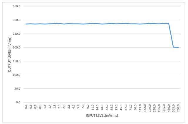
    I also performed a sweep test.
    However, please note that the target gain setting in my test differs from the condition discussed in my original question.
    Also, due to measurement equipment limitations, both the input and output measurements are analog signals.

    In your test, AGC disengagement was observed at low signal levels.
    I could not confirm that behavior on my side.
    However, I believe the reason is simply that my measurement equipment cannot generate sufficiently low input levels.
    In my measurements, the AGC remained active over the entire input range, and the output level stayed nearly constant.
    Also, this output level is higher than the configured target gain, which is the issue I am investigating.
    I believe your measurement results and mine are consistent in many aspects.

    1.In your measurements, the transition from approximately -45dBrG to -2dBFS appears to indicate that the AGC became active.
    There may be discussion regarding the input level at which AGC becomes active, but I do not believe that point is strongly related to the main issue.

    2.In your measurements, from approximately -43dBFS input up to 0dBFS input, although there are some partial level reductions, the output remains approximately constant at -2dBFS, which suggests that AGC is operating.
    Also, since this is approximately +6dB higher than the target setting of -10dBFS, I believe this behavior matches the phenomenon I am observing.

    There are also some differences between our measurements.

    1.In your measurements, the level drops toward approximately -10dBFS around -25dBrG, but I could not observe this behavior in my measurements.
    One possible reason may be that our measurement points are different.
    You mentioned that you are measuring the ADC output, so I assume you are observing the digital data after AGC processing.
    In my case, I am measuring the analog signal after the digital data passes through the DAC.
    This difference may be one contributing factor.


    2.In my measurements, the level begins to decrease once the input exceeds approximately 450mVrms.
    When I checked this using an oscilloscope, waveform distortion was visible and the peak voltage was reduced.
    Therefore, I believe the level reduction is caused by waveform distortion.
    In your measurements, I assume that 0dBrG corresponds to the target gain, so input levels above the target gain may not have been tested.


    One concern I have is regarding your measurement point.
    Since this is fundamentally the behavior of the IC itself, I believe it would be better to evaluate both the input and output using analog signals.
    Also, I believe it would be useful to test input levels higher than the target gain.
    My understanding is that AGC is intended to maintain a nearly constant output level over a wide range of input levels, from below the target level to above the target level.
    Therefore, if the input signal exceeds the target level, the AGC should apply negative gain adjustment in order to maintain a constant output level.

    Kind regards

  • Hi,

    My measurements do include when the input is over the target level, dBrG is with respect to full scale, not the target level. I do agree with your results, the output should decrease when input exceeds the target. I can try again with a lower target, since -10dB may actually be -4dB, this is close to full scale. 

    I also tried to get this to work with a differential signal, to verify the target levels of the AGC with differential input, but was having some issues with the script as is. I might need to try again to get that working. That would help confirm what signal the AGC is looking at, and is the gain always 6dB off or just for single ended.

    Analog output vs digital output of the AGC should not have a big effect on the operation of AGC, my differences from yours may be due to measurement error. DAC behavior should be linear across frequency.

    -Mir

  • Hi,

    Thank you for continuing the investigation.
    Could you also provide clarification regarding the following points?

    1.Is this AGC intentionally designed so that the output level becomes higher than the configured target level?
    Would it be possible to check with the IC design team regarding this behavior?
    For example, I understand that the difference between average value and RMS value, which you explained earlier, is one reason why the output does not exactly match the target gain.
    However, that effect is only about 11% (approximately 1 dB), so I believe there must be another reason for the remaining discrepancy.

    2.If the output level is intentionally higher, what tolerance should be expected?
    For example, currently the output level is approximately 6 dB higher than the target level.
    Could another IC lot under the same conditions instead produce a result 6 dB lower than the target level?

    If this IC always outputs approximately 6 dB higher than the target level for a steady sine wave or pseudo-audio signal according to the intended algorithm, then this is not necessarily a problem for us.
    In that case, we can simply compensate by adjusting the signal levels before and after the IC.
    My concern is whether this approximately +6 dB output variation changes depending on IC lot variation or each power cycle.
    At least, since both your measurement environment and mine reproduce similar behavior, it appears that the behavior is not randomly changing between IC lots or each time power is applied.
    However, I would like confirmation from the IC design perspective in order to guarantee this behavior.
    What I most want to understand is whether the observed measurement results are consistent with the theoretical behavior based on the mechanism causing this phenomenon.
    However, if analyzing the exact mechanism is difficult, then I would at least like to understand how much variation in the measured results can be expected or guaranteed.
    Since quite some time has passed since I first started asking about this issue, I would appreciate receiving a conclusion as soon as possible.

    Kind regards

  • Hi,

    My coworkers and I believe that the increase in output level when the input exceeds the target may have to do with the 6dB discrepancy we were seeing before. I was trying to verify this earlier today by checking if the discrepancy was still there when AGC is off but I was having some issues with my setup and the audio was distorted. I will try again tomorrow to verify. In your sweep measurement, I see that the output changes around when the input reaches -6dB. So, this issue may be caused by that single ended/differential issue, something with the ADC and the level that it is passing to the AGC. I am sorry I was not able to verify today.

    I would expect that this measurement that we are seeing would be present on all devices, this is not a known "issue" with the chip, but it is just how it works with this register setup and hardware configuration. I want to verify the "why" now. We expect that the AGC receives the digital data from the ADC itself, so it is a digital audio issue that we are seeing, not analog. The digital should always behave the same way when it is programmed the same, which should prove that all chips will behave this way with our script.

    One more question I have for you - can you send the script that you are using to configure the device? Or are you just sending it your register dump you sent me? The order of commands can potentially vary the result when it is run.

    Best,
    Mir

  • Hi,

    I apologize, but I did not save the script data when I captured the dump data that I sent previously.

    I am attaching the script data and the corresponding dump data from my current setup, where I confirmed the approximately +6 dB output level behavior.

    Regarding your comment below, could you clarify what you mean?

    "In your sweep measurement, I see that the output changes around when the input reaches -6dB."

    In my sweep test, the target gain was set to -14 dB, which corresponds to approximately 141 mVrms when calculated from a full-scale level of 0.707 Vrms.

    In my measurement results, the output remains essentially constant from approximately 0.6 mVrms up to 450 mVrms input, and then begins to decrease between approximately 565 mVrms and 700 mVrms input.

    Could you clarify which part of my measurement results you are referring to when you mention "-6 dB"?

    Kind regards,

    i i2cfast
    w 30 13 40
    w 30 13 00
    w 30 13 04
    w 30 08 80
    w 30 08 C0
    w 30 1A 80
    w 30 1A C0
    w 30 07 88
    w 30 25 80
    w 30 29 40
    w 30 2B 00
    w 30 56 18
    w 30 56 19


    w 30 15 40
    w 30 15 00
    w 30 16 7C
    w 30 1D 80
    w 30 1D C0
    w 30 07 8A
    w 30 25 C0
    w 30 29 50
    w 30 2C 00
    w 30 5D 18
    w 30 5D 19
    w 30 56 08
    w 30 56 09
    w 30 5D 01
    w 30 5D 09
    w 30 07 88
    w 30 07 8A
    w 30 25 80
    w 30 25 C0
    w 30 29 40
    w 30 29 50
    w 30 2C 00
    w 30 2B 00
    w 30 1A 80
    w 30 1D 80
    w 30 1D C0
    w 30 1A C0
    w 30 08 40
    w 30 08 C0
    w 30 13 40
    w 30 15 40
    w 30 15 00
    w 30 13 00
    w 30 15 78
    w 30 15 78
    w 30 16 40
    w 30 16 00
    w 30 15 78
    w 30 13 04
    w 30 16 04
    w 30 0F 00
    w 30 10 00
    

    0763.reg.csv

  • Hi,

    I did this test again with both differential and single ended ADC configurations, just to see what happens with the AGC. I found that for BOTH single ended and differential, we see the AGC kick in ~6dB higher than we expect. So, I have the script set to -14dB threshold here, and AGC starts around -7dB (-8dB is 6 off, plus 1dB of difference for gain error plus averaging/rms difference).

    The curve on the left is the single ended signal, and curves on the right are differential (with one measurement taken with no AGC on, just to make sure we are measuring correctly).

    w 30 01 80 #reset
    w 30 07 80 #reset
    w 30 0F 00 #ladc pga not muted, 0db gain
    w 30 13 04 #single ended, 0db gain, ladc powered up
    w 30 13 84 #differential, 0db gain, powered up
    
    # w 30 08 C0 #bclk and wclk are output
    w 30 1A C0 #lagc enabled, target = -14dB
    w 30 07 88 #44.1 mode, ldac data plays left channel
    w 30 25 80 #ldac powered up
    w 30 29 40 #ldac to dac_l3 (left line out)
    w 30 2B 00 #ldac not muted, 0db gain
    w 30 56 19 #left_lop output = 1dB, not muted, fully powered up
    

    Here is the script I used, did BCLK and WCLK input since that is easier on my setup. I commented out the line setting register 0x13 to differential mode to test in single ended.

    I think the algorithm is just 6dB off, I don't think we can change it. If you do want the AGC to threshold at -14dB, you should set the -20dB setting and it will be 6dB higher.

    Let me know what you think or if you need more help. I can start a process of changing the datasheets after a bit more testing to verify...

    Best,
    Mir

  • Hi,

    You indicated that the approximately 6 dB discrepancy may be caused by the AGC algorithm itself and that it may not be possible to correct it.
    Could you please clarify the following points?

    1.Should this behavior be considered an intended design characteristic of the device?

    2.Was this conclusion based on results obtained from multiple samples?
    In other words, can we rule out the possibility of a defective device?

    3.What level of variation would you expect between different lots and individual devices?

    4.Could you explain what the AGC target gain actually represents?
    Since a sine wave input produces an output level approximately 6 dB higher than the configured target gain, I assume the target gain may be based on a different reference or measurement method.

    Kind regards,

  • Hi,

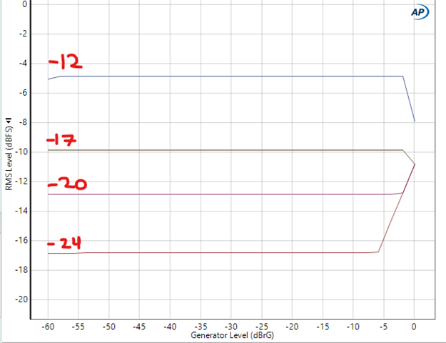
    I want to update my original graphs - here is a reading of the AGC set to -24dB target and sweeping from -60dB to 0dB of input. In my previous measurement, I had not set all AGC parameters and had the timing wrong on my measurement software and it seemed like it was not applying gain, just reducing gain when the input was over the target. Now, I have updated the script and the output is more accurate, except for the 6dB offset. It seems like around -6dB generator level, the AGC cannot keep the volume down, and it increases linearly. I saw in this app note about similar devices (link) that the minimum PGA gain is -12dB, so this would make sense for the -6dB signal to be brought down to ~-18dB by the PGA, and then when the input signal exceeds that, it still has -12dB of gain but not more, so that is why the gain increases linearly at the highest ADC input levels.

    I then measured the AGC for various input threshold levels (changing register 0x1a):

    We see the same ~6dB offset on all of them.

    I saw at least 1 other E2E thread about this issue, but not as in depth as the discussion we are having here. I have measured on 2 different devices from the same family and seen the same response so I believe this is how the AGC algorithm works. From my various testing, I believe that this 6dB offset is from the AGC algorithm, not the ADC settings or measurement error.

    I can reach out to design team for more explanation, but I am worried they will not have the bandwidth to give a real answer/solution since this is an older part. In the meantime, I would recommend just setting the level to what you desire in your end application - make sure you test with an example of the audio you expect to record with the ADC, and now we know that the AGC level is about 6dB off from the expected level. Ideally, AGC is used in a specific scenario where you know the type of signals that could come through your microphone, so you can set the noise threshold and the target level based on that.

    Here is my script I used for reference: 

    w 30 00 00 #page 0
    w 30 01 80 #reset
    w 30 07 80 #reset
    d 100
    
    w 30 0F 00 #ladc pga not muted, 0db gain
    w 30 13 04 #single ended, 0db gain, ladc powered up
    # w 30 08 C0 #bclk and wclk are output
    
    
    # w 30 1a f0 #-24dB target level
    w 30 1a e0 #-20dB target level
    # w 30 1a d0 #-17dB target level
    # w 30 1A C0 #-14dB target level
    # w 30 1a b0 #-12dB target level
    # w 30 1a a0 #-10dB target
    # w 30 1a 90 #-8dB target
    # w 30 1a 80 #-5.5dB target
    
    w 30 1b fe #max gain = 59.5 dB
    w 30 1c c0 #hysteresis and silence detection disabled
    
    w 30 07 88 #44.1 mode, ldac data plays left channel
    w 30 07 08 #48k mode
    
    w 30 25 80 #ldac powered up
    w 30 29 40 #ldac to dac_l3 (left line out)
    w 30 2B 00 #ldac not muted, 0db gain
    w 30 56 19 #left_lop output = 1dB, not muted, fully powered up
    

    Best,
    Mir

  • Hi,

    Thank you for your investigation and for sharing the results.
    Based on your findings, we will consider our design while taking the approximately 6 dB offset into account.
    Could you please help clarify the following points?

    1.What tolerance should we expect for this 6 dB offset?
    Would it be reasonable to assume a variation of approximately ±1 dB?
    The expected variation is important for our level budget and system design.

    2.In a previous reply, you mentioned the possibility of updating the datasheet based on this investigation.
    What kind of changes would be expected in the datasheet?

    3.If the datasheet is updated, how long does the revision process typically take before a new version is released?

    4.Could you please check with the design team regarding what the AGC target gain actually represents?
    Since we consistently observe an output level approximately 6 dB higher than the configured target gain, it seems possible that the target gain is based on a different internal reference or measurement method.

    Regarding questions 2 and 3, having this 6 dB offset explicitly documented in the datasheet would provide strong justification when explaining the behavior to our customers.
    If possible, I would also appreciate having the expected tolerance of this offset documented as well.

    Kind regards,

  • Hi,

    The expert for this device is out of office and can respond later this week.

    Best,

    Garret

  • Hi,

    1: the device can have ~1dB of gain error, plus the ~1dB of abs average vs RMS signal error with the AGC detection algorithm. So, I would assume variation of up to 2dB. In my measurements, it was ~7dB of offset from what we expect with the AGC target. +/-1dB seems reasonable to assume, maybe up to 1.5dB both directions.

    2 and 3: We would change the AGC target levels in the register map (page 0 reg 26 and 29). It may take over a month since I need to reach out to design to verify but they are busy with newer parts, and then complete all checks with datasheet edits.

    4: working on it. It does seem like this is based on a different reference/method. However since we see the same behavior with the same script, we can assume that the behavior we see is what will happen on all boards with the script we are using.

    Best,
    Mir 

  • Hi,

    I believe the investigation of the observed behavior is sufficiently complete for now.

    Thank you for your support and for the detailed investigation.

    Please let me know if there are any updates regarding the following items:

    1.Completion of the datasheet revision, or any progress related to the datasheet update.
    2.Any findings from the design team regarding the AGC target gain definition and implementation.

    I understand that these items may take some time to investigate.

    For now, I would prefer not to mark this thread as resolved, since I am not sure whether I would continue to receive email notifications after the thread is resolved.

    I am not very familiar with how the E2E notification system works, so please let me know if keeping the thread open would cause any issues.

    Kind regards,

  • Hi,

    No issues with leaving it open, just don't respond to this unless you do have a new question for me! I will update you here and you should get notified.

    Best,
    Mir