Part Number: TAS3251
i have a question and i will be grateful if you can help me.
main project: connecting STM32H743 to TAS3251 and playing an mp3 file saved on a usb flash which is connected to stm32.
problem: cant get dsp to work. (tas3251 plays the song also i can change its volume by 0x3d and 0x3e but i cant get the dsp to work)
what i have done up to now:
i decode the mp3 file on the usb flash connected to stm32. i connect the i2s pins of stm32 to the ta3251 (4 wires- i also generate the MCLK) and i play the music successfully. also i can change the volume by varying the number written for 0x3d and 0x3e. i send you the TAS3251_init function which i wrote up to now:
void TAS3251_LoadRegisters(const cfg_reg *r, uint16_t size)
{
for(uint16_t i=0;i<size;i++)
{
HAL_I2C_Mem_Write(&hi2c3,TAS_ADDR,r[i].reg,I2C_MEMADD_SIZE_8BIT,(uint8_t*)&r[i].val,1,HAL_MAX_DELAY);
HAL_Delay(1);
}
}
cfg_reg registers[] = {
//program memory
{ 0x00, 0x00 },
{ 0x7f, 0x00 },
{ 0x02, 0x11 }, //PowerDown DSP. Bit 0 not documented
{ 0x01, 0x11 }, //Reset module & registers. Bits are auto cleared
{ 0x00, 0x00 }, //Wait
{ 0x00, 0x00 },
{ 0x00, 0x00 },
{ 0x00, 0x00 },
{ 0x03, 0x11 }, //Mute L&R
{ 0x2a, 0x00 }, //Zero Data path L&R (= mute...)
{ 0x25, 0x18 }, //Ignore MCLK error detection
{ 0x0d, 0x00 }, //Clck config..
{ 0x28, 0x00 }, //I2S config
{ 0x29, 0x01 },
{ 0x02, 0x00 }, //Wake up DSP
//Sample rate update
{ 0x00, 0x00 },
{ 0x7f, 0x00 },
{ 0x02, 0x80 }, //Reset DSP
{ 0x00, 0x00 },
{ 0x7f, 0x00 },
// speed 03-48k 04-96k
//dynamically reading speed
{ 0x22, 0x03 }, //Set FS Speed. Ignored in auto clock mode
{ 0x00, 0x00 },
{ 0x7f, 0x00 },
{ 0x02, 0x00 }, //Restart DSP
//register tuning
{ 0x00, 0x00 },
{ 0x7f, 0x00 },
{ 0x00, 0x00 },
{ 0x07, 0x00 },
{ 0x08, 0x20 },
{ 0x55, 0x07 },
{ 0x00, 0x00 },
{ 0x7f, 0x00 },
{ 0x00, 0x00 },
{ 0x3d, 0x50 }, //volume
{ 0x3e, 0x50 }, //volume
{ 0x00, 0x00 },
{ 0x7f, 0x00 },
{ 0x00, 0x01 },
{ 0x02, 0x00 },
//Unmute the device
{ 0x00, 0x00 },
{ 0x7f, 0x00 },
{ 0x03, 0x00 },
{ 0x2a, 0x11 },
};
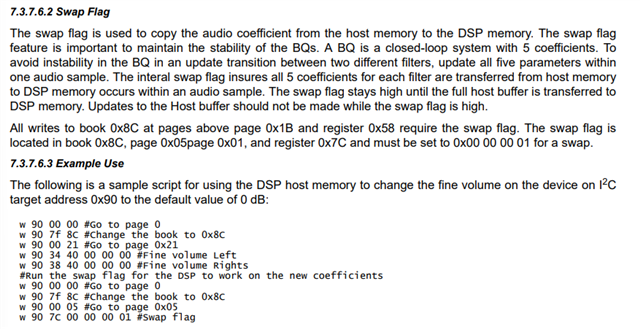
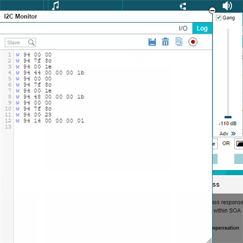
my problem starts from here. i want to start dsp and change the volume by the value written for 0x44 and 0x48 register which are on page 0x8c .
when i change the value of 0x44 and 0x48 nothing happens (the volume doesn't change) for example when i change it to 0 i expect the sound to be muted but it doesn't happen.
i send you the second init function which i wrote to get the dsp to work:
cfg_reg registers[] = {
//program memory
{ 0x00, 0x00 },
{ 0x7f, 0x00 },
{ 0x02, 0x11 }, //PowerDown DSP. Bit 0 not documented
{ 0x01, 0x11 }, //Reset module & registers. Bits are auto cleared
{ 0x00, 0x00 }, //Wait
{ 0x00, 0x00 },
{ 0x00, 0x00 },
{ 0x00, 0x00 },
{ 0x03, 0x11 }, //Mute L&R
{ 0x2a, 0x00 }, //Zero Data path L&R (= mute...)
{ 0x25, 0x18 }, //Ignore MCLK error detection
{ 0x0d, 0x00 }, //Clck config..
{ 0x28, 0x00 }, //I2S config
{ 0x29, 0x01 },
{ 0x02, 0x00 }, //Wake up DSP
//Sample rate update
{ 0x00, 0x00 },
{ 0x7f, 0x00 },
{ 0x02, 0x80 }, //Reset DSP
{ 0x00, 0x00 },
{ 0x7f, 0x00 },
// speed 03-48k 04-96k
//dynamically reading speed
{ 0x22, 0x03 }, //Set FS Speed. Ignored in auto clock mode
{ 0x00, 0x00 },
{ 0x7f, 0x00 },
{ 0x02, 0x00 }, //Restart DSP
//write co-efficients
{ 0x00, 0x00 }, //Change Page
{ 0x7f, 0x8c },
{ 0x00, 0x1e }, //Page 0x1e
{ 0x44, 0x00 }, //VOLUME CONTROL - CH-L Volume
{ 0x45, 0x00 },
{ 0x46, 0x00 },
{ 0x47, 0x00 },
{ 0x00, 0x00 }, //Change Page
{ 0x7f, 0x8c },
{ 0x00, 0x1e }, //Page 0x1e
{ 0x48, 0x00 }, //VOLUME CONTROL - CH-R Volume
{ 0x49, 0x00 },
{ 0x4a, 0x00 },
{ 0x4b, 0x00 },
//swap command
{ 0x00, 0x00 },
{ 0x7f, 0x8c },
{ 0x00, 0x23 },
{ 0x14, 0x00 },
{ 0x15, 0x00 },
{ 0x16, 0x00 },
{ 0x17, 0x01 },
//register tuning
{ 0x00, 0x00 },
{ 0x7f, 0x00 },
{ 0x00, 0x00 },
{ 0x07, 0x00 },
{ 0x08, 0x20 },
{ 0x55, 0x07 },
{ 0x00, 0x00 },
{ 0x7f, 0x00 },
{ 0x00, 0x00 },
{ 0x3d, 0x50 },
{ 0x3e, 0x50 },
{ 0x00, 0x00 },
{ 0x7f, 0x00 },
{ 0x00, 0x01 },
{ 0x02, 0x00 },
//Unmute the device
{ 0x00, 0x00 },
{ 0x7f, 0x00 },
{ 0x03, 0x00 },
{ 0x2a, 0x11 },
};
what can i do in this case.Thanks for attention.