This thread has been locked.

If you have a related question, please click the "Ask a related question" button in the top right corner. The newly created question will be automatically linked to this question.

PCM1863: Request for Support – PCM1863 Microphone Capture No Audio Output

Part Number: PCM1863
Other Parts Discussed in Thread: PCMD3140

Dear TI Team,

We are evaluating PCM1863 for microphone input functionality and encountered an issue where no audio can be captured from the digital output.

Current setup:

  • Device: PCM1863
  • Use case: Microphone input → ADC → Digital Output
  • Digital audio output connected to: GPIO1 (configured as DATA output)
  • I2C communication: Normal
  • Register configuration: Attached below
  • Symptom:
    • Device can be configured successfully through I2C.
    • Clock appears normal.
    • However, no microphone audio can be recorded from the output stream.
  • Hi Luke,

    It looks like the register configuration attachment is missing. What is your number of channels, audio interface, and FSYNC and BCLK frequencies?

    GPIO1 can only be configured as DOUT2, not the main data output, so it is not available in certain modes.

    Best,

    Garret

  • Hi Luke,

    It looks like the register configuration attachment is missing. What is your number of channels, audio interface, and FSYNC and BCLK frequencies?

    GPIO1 can only be configured as DOUT2, not the main data output, so it is not available in certain modes.

    Best,

    Garret

    Hi Garret,

    Thank you for your reply.

    We would also like to provide one additional observation:

    LRCK=48K

    BCLK=3.072M 

    With the current register configuration, our understanding is that the PDM microphone data path is configured through GPIO1.

    In this case:

    • PDM microphone connected to GPIO1 → No audio can be recorded
    • PDM microphone connected to GPIO0 → Audio recording works normally

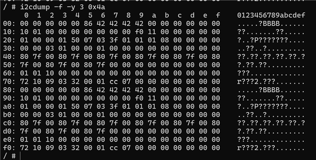
    The register dump and configuration screenshot are attached.

    Thank you for your support.

    Best regards,
    Luke

  • Hi Luke,

    On PCM1863, 2 channel ADC + 2 channel PDM is not a supported use case. It looks like you have this enabled, which could be causing a conflict on DOUT when GPIO1 is configured and used as PDM input. 

    Best,

    Garret

  • Hi Garret,

    Thank you for your explanation.

    I think my previous description may have caused some confusion.

    To clarify: we do NOT intend to use 2-channel ADC and 2-channel PDM simultaneously.Our intended use case is only PDM microphone capture, and the analog ADC path is not needed during this test.

    Could you please help clarify:

    1. For PDM-only use case, what registers or blocks should be disabled to ensure ADC is completely turned off?
    2. Is GPIO1 supported as PDM input in PDM-only mode?
    3. If supported, is there a recommended configuration sequence or register settings?

    Thanks

    Luke

  • Hi Luke,

    Today is a US holiday, so responses will be delayed.

    Best,

    Garret

  • Hi Luke,

    This function can be selected by register for each ADC input selection, ADCX1_INPUT_SEL_X (Page.0, 0x06 → 0x09) setting to 0x40 to Mute the ADC.

    Yes, GPIO1 can support a PDM input.

    You need to utilize the post-ADC processing mixers to enable this. Enable the DIN inputs on the mixer:

    This requires to write to the DSP, which is described in detail on page 68 of the datasheet, with support tool here: https://www.ti.com/tool/download/SLAC663

    Best,

    Garret

  • Hi Garret,

    Thank you for your explanation.

    Based on your suggestion, I understand that I need to set the coefficients of I2S_L and I2S_R in mixer1 to values ​​corresponding to 0dB. I referred to SLAC663 and set the relevant registers, but I didn't record any sound. You can see my setup steps in the image.

    In addition, I also tried setting the gain of MIX1_CH1L, MIX1_CH1R, MIX1_CH2L, and MIX1_CH2R to -120dB, and setting MIX1_I2SL and MIX1_I2SR to 0dB, but still no sound was recorded.

    I tried the same settings in mixer2, with the same result.

    Is there something wrong with my understanding? Could you tell me where the problem lies?

  • Hi Luke,

    Did you switch the PDM input back to GPIO1?

    Is there a particular reason PCM1863 was selected for this application? PDM input applications are much more straightforward on a newer device like PCMD3140.

    Best,

    Garret

  • Hi Garret,

    Yes, we switched the PDM input back to GPIO1.

    We selected PCM1863 because we need a high-performance TI audio ADC for this design. However, we still need to use the ADC for PDM microphone input, so we would like to confirm whether PCM1863 has any known issue or limitation in this use case.

    Our current test result is unexpected:

    • Register settings: 0x10 = 0x10, 0x11 = 0x01, 0x1A = 0x11
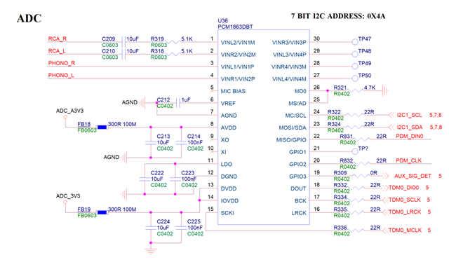
    • PDM CLK is connected to GPIO2 / pin 20
    • PDM DATA connected to GPIO1 / pin 21: no audio
    • PDM DATA connected to GPIO0 / pin 22: audio can be recorded

    Based on the datasheet, this configuration should select GPIO1 as the PDM data input. Could you please confirm whether PCM1863 supports PDM DATA input on GPIO1 / pin 21, and whether GPIO0 / pin 22 is a valid and production-safe option for PCM1863?

    Best regards,
    Luke

  • Yes, PDM data is supported on GPIO1 and GPIO0. What is the result if you configure the registers for GPIO0? Does the PDM data output audio on GPIO0 or GPIO1? This could be a mixer issue that is swapping the data between these pins.

  • Hi Garret,

    Without adjusting the Mixer Coeff,

    if write register: 0x1a data: 0x11,

    write register: 0x10 data: 0x10,

    write register: 0x11 data: 0x21,

    sound can be recorded from GPIO0.

    If write register: 0x1a data: 0x01,

    write register: 0x10 data: 0x01,

    write register: 0x11 data: 0x21,

    sound cannot be recorded from GPIO0.

    This is contrary to my expectations.

  • and

    I've been trying to record audio from GPIO1 for the past few days. My steps are listed below, but it still doesn't work. Could you please help me figure out what the problem is?

    Write register: 0x00 Data: 0xfe

    Write register: 0x06 Data: 0x40

    Write register: 0x07 Data: 0x40

    Write register: 0x08 Data: 0x40

    Write register: 0x09 Data: 0x40

    Write register: 0x10 Data: 0x10

    Write register: 0x11 Data: 0x21

    Write register: 0x19 Data: 0xf0 (Also tried 0x00 and 0xff)

    Write register: 0x1a Data: 0x11

    GPIO2 outputs PDM_CLK at a frequency of 3.072MHz, and PDM_DATA is connected to GPIO1 (Pin 21) of the PCM1863.

    The digital microphone is working in right channel mode (L/R pins connected to VDD) and is functioning correctly, as the PDM_DATA waveform can be measured.

    A waveform is output on the DOUT pin of the PCM1863, but the waveform remains unchanged, and no sound is detected.

    Then I wrote register 0x00 to data 0x01, entering page 1.

    I used R_REQ to check the Mixer Coeff settings. I found that CH1_L was set to 0dB in mixer1, and the other channels were muted; CH1_R was set to 0dB in mixer2, and the other channels were muted. As you mentioned, the DIN channel is not enabled.

    Then I used W_REQ to set the Mixer Coeff, enabling the DIN channel. However, there was still no sound; the waveform on the DOUT pin remained unchanged.

    Subsequently, I muted CH1_L and CH1_R, and the waveform on the DOUT pin disappeared, remaining at a low level. It appears that I2S_L and I2S_R are not sending data to the mixer.

    Then I wrote data 0x00 to register 0x00, entered page 0, and wrote data 0x60 to register 0x10, changing the function of GPIO1 from digital microphone input to DIN. At this point, a waveform appeared on the DOUT pin, and it kept changing. This setting is clearly incorrect, as the sound is noise. I did this only to confirm that I2S_L and I2S_R were correctly connected to the mixer, and the result was yes; I2S_L and I2S_R are indeed correctly connected to the mixer.

    I repeatedly confirmed that PDM_DATA is indeed connected to GPIO1 in hardware. The problem seems to be that the digital microphone data is not connected to I2S_L and I2S_R.

    Could you point out where the problem lies?

    Best regards, Luke

  • Hi Luke,

    Garret is out of office today and will follow up with you tomorrow U.S. time.

    Thanks for your patience,
    Jeff McPherson

  • Hi TI Team

    any update ?

  • Hi Luke,

    Sorry for the delay, I am still looking into this.

    Best,

    Garret

  • Hi Luke,

    Can you try with this script?

    w 94 00 01
    w 94 00 01
    w 94 00 01
    r 94 01 01
    w 94 02 00 
    w 94 04 00 00 01 00 
    w 94 01 01
    
    w 94 00 01
    w 94 00 01
    w 94 00 01
    r 94 01 01
    w 94 02 04 
    w 94 04 10 00 00 00 
    w 94 01 01
    
    w 94 00 01
    w 94 00 01
    w 94 00 01
    r 94 01 01
    w 94 02 07 
    w 94 04 00 00 01 00 
    w 94 01 01
    
    w 94 00 01
    w 94 00 01
    w 94 00 01
    r 94 01 01
    w 94 02 0b
    w 94 04 10 00 00 00 
    w 94 01 01 

    Best,

    Garret

  • Hi Garret,

    Thank you for your response.

    I followed the register configuration steps you provided for the PCM1863, but I still cannot record audio from GPIO1. The waveform on the DOUT pin remains unchanged and does not reflect any data from the digital microphone. You can find my configuration steps in the attachment.

    A few days ago, I applied for 10 PCM1863 samples from the TI website, and I received them today. I tested again using these new samples, and the result is the same, which confirms that my PCM1863 devices are not counterfeit.

    I have made a new observation: I found a way to successfully record audio from GPIO1, but this method does not use the Mixer Coefficient settings. My register configuration is listed below:

    Write register: 0x00 Data: 0xFE
    Write registers: 0x06 / 0x07 / 0x08 / 0x09 Data: 0x40
    Write register: 0x10 Data: 0x10 (configure GPIO1 as digital microphone input, GPIO0 as GPIO)
    Write register: 0x11 Data: 0x21 (configure GPIO2 as digital microphone clock output)
    Write register: 0x19 Data: 0xF0

    The key point is the configuration of register 0x1A:

    If I write register 0x1A = 0x11 (set Digital Mic Data Input to GPIO1), I can record audio from GPIO0, but not from GPIO1.
    If I write register 0x1A = 0x01 (set Digital Mic Data Input to GPIO0), I can record audio from GPIO1, but not from GPIO0.

    This behavior is the opposite of what is described in the datasheet.

    I have the following hypotheses, and I would appreciate your help in verifying whether they are correct:

    The datasheet may have the GPIO0 and GPIO1 mapping in register 0x1A reversed, or there may have been a misalignment during channel mapping. This would explain why when GPIO1 is configured as input, audio can only be recorded from GPIO0, and vice versa when GPIO0 is configured as input.
    As I mentioned in my previous email, during earlier tests I observed that the digital microphone data does not appear on I2S_L and I2S_R. The datasheet repeatedly states that the digital microphone input passes through the Digital PGA, and in Figures 26 and 27, the digital microphone data and ADC audio data share the same path into the Digital PGA. However, on page 33 in the PCM signal description, it states: “The incoming data are then driven to the digital mixer running on DSP2”, which implies that the I2S signal is driven from the DIN pin into the mixer and does not pass through the Digital PGA. This suggests that the digital microphone path and the I2S path are not the same. The digital microphone data may actually use the CH1_L and CH1_R channels, while the I2S signal clearly uses the I2S_L and I2S_R channels.

    I would appreciate it if you could help confirm whether these assumptions are correct.

    Best regards,
    Luke

    The I2C address of the PCM1863 is 0x4a
    
    / # i2cset -f -y 3 0x4a 0x00 0xfe
    / # i2cset -f -y 3 0x4a 0x06 0x40
    / # i2cset -f -y 3 0x4a 0x07 0x40
    / # i2cset -f -y 3 0x4a 0x08 0x40
    / # i2cset -f -y 3 0x4a 0x09 0x40
    / # i2cset -f -y 3 0x4a 0x10 0x10
    / # i2cset -f -y 3 0x4a 0x11 0x21
    / # i2cset -f -y 3 0x4a 0x19 0xf0
    / # i2cset -f -y 3 0x4a 0x1a 0x11
    
    
    / # i2cset -f -y 3 0x4a 0x00 0x01
    / # i2cset -f -y 3 0x4a 0x00 0x01
    / # i2cset -f -y 3 0x4a 0x00 0x01
    / # i2cget -f -y 3 0x4a 0x01
    0x00
    / # i2cset -f -y 3 0x4a 0x02 0x00
    / # i2cset -f -y 3 0x4a 0x04 0x00 0x00 0x01 0x00 i
    / # i2cset -f -y 3 0x4a 0x01 0x01
    / #
    / #
    / #
    / # i2cset -f -y 3 0x4a 0x00 0x01
    / # i2cset -f -y 3 0x4a 0x00 0x01
    / # i2cset -f -y 3 0x4a 0x00 0x01
    / # i2cget -f -y 3 0x4a 0x01
    0x00
    / # i2cset -f -y 3 0x4a 0x02 0x04
    / # i2cset -f -y 3 0x4a 0x04 0x10 0x00 0x00 0x00 i
    / # i2cset -f -y 3 0x4a 0x01 0x01
    / #
    / #
    / #
    / # i2cset -f -y 3 0x4a 0x00 0x01
    / # i2cset -f -y 3 0x4a 0x00 0x01
    / # i2cset -f -y 3 0x4a 0x00 0x01
    / # i2cget -f -y 3 0x4a 0x01
    0x00
    / # i2cset -f -y 3 0x4a 0x02 0x07
    / # i2cset -f -y 3 0x4a 0x04 0x00 0x00 0x01 0x00 i
    / # i2cset -f -y 3 0x4a 0x01 0x01
    / #
    / #
    / #
    / # i2cset -f -y 3 0x4a 0x00 0x01
    / # i2cset -f -y 3 0x4a 0x00 0x01
    / # i2cset -f -y 3 0x4a 0x00 0x01
    / # i2cget -f -y 3 0x4a 0x01
    0x00
    / # i2cset -f -y 3 0x4a 0x02 0x0b
    / # i2cset -f -y 3 0x4a 0x04 0x10 0x00 0x00 0x00 i
    / # i2cset -f -y 3 0x4a 0x01 0x01

  • Hi Luke,

    I need to pass this support to a colleague who can respond to your questions.

    Best,

    Garret