This thread has been locked.

If you have a related question, please click the "Ask a related question" button in the top right corner. The newly created question will be automatically linked to this question.

TAS2574EVM: TAS2574 PPC3 OCP Latch and missing features

Part Number: TAS2574EVM
Other Parts Discussed in Thread: TAS2574

I am running into issues where the TAS2574EVM is succesfully playing back audio but with certain peak dynamic content, it Latches and needs to be reset for playback to funciton again. I've Read the registers and found that the OCP has been triggered. I am still adjusting settings of the Channel Gain and Boost functions, but found a discrepancy in the EVM User's Guide and what I'm actually seeing in the PPC3 console.

1 - Any guidance on how to optimize Channel Gain/Boost settings?  The application is a 10Wavg rated loudspeaker that can handle plenty of peak power but the application is a battery operated (1S) that will be running off a 5V rail.  I've measure voltage output when the Latch happens and it's not even crossing 4V.

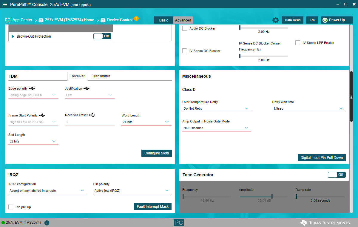
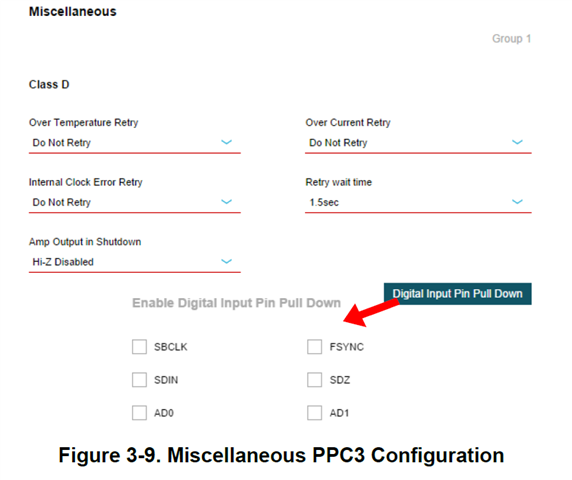
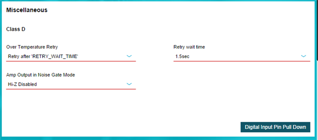
2 - How do I make sure my board is actually being read by PPC3 as the TAS2574?  The user's guide states there is a Over Current Retry but it doesn't show up in PPC3.

Below is the info on what I'm seeing in PPC3.
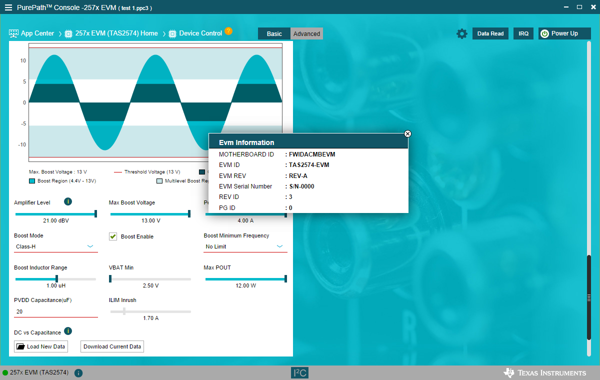
image.png


image.png


  • Hi Doug,

    Well received your requests, I will investigate and get back to you with feedbacks ASAP. Thanks.

  • Update: I referred to another TAS2574 support question and programmed the part number (per Peter Wu5's instructions), reset the AC-MB and was able to choose TAS2574 as the part number in the next session. So, now PPC3 identifies it as a TAS2574 but there is still a misalignment in features in the EVM user manual and what I see in PPC3.  The images I previously posted are still the same.

  • Hi Doug,

    You can set boost voltage to 13V and amplifier level to 18dBV to avoid clipping and OCP issue. Thanks.

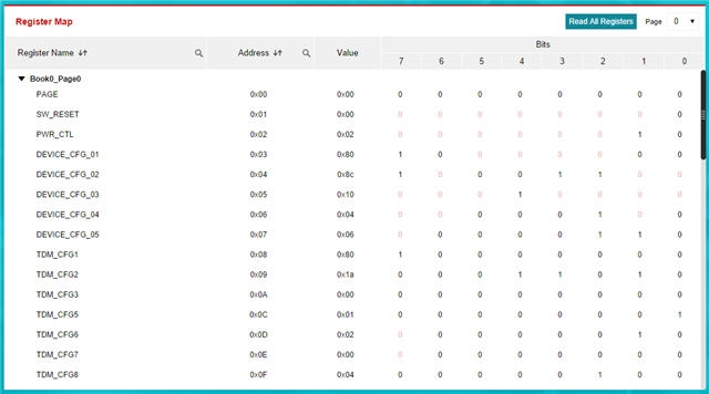
  • I have tried the settings but I still get the same errors.  See attached register map.

    I'll ask again. Is there any idea why I'm not seeing the OCP 

    EVM User guide says Miscellaneous has these features:

    But, this is all I see in PPC3:

  • Hi Doug,

    First, it is important to clarify that OCP (Over-Current Protection) is triggered by peak output current, not output voltage. Even at output voltages below 4V, high transient current spikes from dynamic audio content, excessive gain, or misconfigured boost/limiter settings can trip the protection threshold and cause a latched shutdown.
    For your 1S battery / 5V rail application with a 10W rated loudspeaker, follow this step-by-step optimization workflow:
    Your current configuration (13V max boost, 12W max POUT, 4A ILIM) uses full-scale values that deliver far more headroom than your 10W speaker requires, and this is the primary cause of unnecessary OCP trips.
    • Reduce Max Boost Voltage from 13V to 9–10V. For a typical 4Ω 10W loudspeaker, ~9V of boost headroom is fully sufficient. Higher boost voltages only increase peak current stress with no practical loudness benefit for your power target.
    • Reduce Max POUT from 12W to 10W. The on-chip power limiter will clamp output peaks before they reach the OCP fault threshold.
    • Reduce ILIM (boost inductor peak current limit) from 4.0A to 3.0–3.5A. This lets the cycle-by-cycle current limit activate before the latched OCP fault triggers.
    • Verify the actual boost inductor on your EVM matches the 1.0µH value set in PPC3. An undersized inductor will increase current ripple and cause false OCP events.

    You currently have Brown-Out Protection disabled. Enabling this feature will proactively limit output power when the battery voltage dips, preventing the high-current / low-voltage conditions that commonly trigger OCP in 1S battery designs.

    If OCP still trips after the above adjustments, probe the PVDD rail and output current with an oscilloscope at the moment of the fault. Narrow, high-amplitude current spikes are often caused by layout parasitics in the speaker loop or boost path; adding an RC snubber or optimizing the high-current path layout will usually resolve this.

  • Echo to your OCP missing question. This is a GUI limitation of the current PPC3 257x plug-in, not a hardware or silicon limitation. the Basic GUI tab only exposes the Over Temperature Retry graphical control; the OCP retry configuration was not mapped to a visible control on this page. Switch to the Advanced tab at the top of the Device Control page, where you can directly access and modify all device registers.