PCM2706C: Confirm pins for self-powered I2S output pcm2706C

Part Number: PCM2706C

Hi, I am desigining an audio device usb peripheral using the PCM2706C.


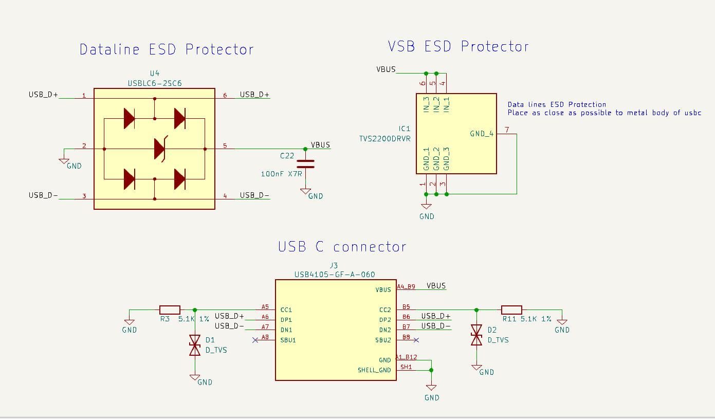
I have a few questions about some of the pins used for my application.  My device is self powered, and does not need to sink any current from the host.  I am not using eeprom to load any config, and am outputting I2S.  The device connector is a usbC 16 pin (and CC1/CC2 are pulled down to ground with 5.1K Resistors)


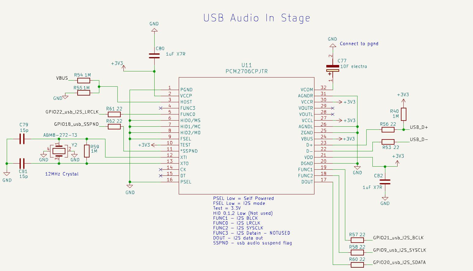
1.  In this situation, I am not sure what to tie HOST to, do I need to tie it to both VBUS and Ground (with 1M resistors) like the attached?


2.  Do I need the pull up on D+ (R40) to 3.3V (3.3V is the main Vdd)


3.  If I am not using VOUTL or VOUTR (as I am using I2S), can I let these float?


4.  If I am not using the DAC, do I need a big 10uF cap on VCOM, or can I tie that somewhere/let it float


5.  Same on VCCL, VCCR, can I just tie these to Vdd (3.3V)?


6.  Do I tie the VBUS pin to my system 5V, 3.3V or the actual USB connector vbus pin?


7.  FUNC3, CK, DT allowed to float as they are not used?


Otherwise does my schematic contain any obvious flaws/misunderstandings?


Thanks very much for your help in this, I appreciate your help.
 

pcm2706C.pngusbconn_and_esd.png

  • Hello Joe, below each question please find the answer.

    1. In this situation, I am not sure what to tie HOST to, do I need to tie it to both VBUS and Ground (with 1M resistors) like the attached.

         For self-powered operation, the HOST pin must be connected to VBUS of the USB bus with a pulldown resistor to detect attach and detach.

     2. Do I need the pull up on D+ (R40) to 3.3V (3.3V is the main Vdd)

      Yes, D+ should be pulled up with a 1.5-kΩ (±5%) resistor.

    3.  If I am not using VOUTL or VOUTR (as I am using I2S), can I let these float?

       Analog outputs in general can be left alone (left float)

     4.  If I am not using the DAC, do I need a big 10uF cap on VCOM, or can I tie that somewhere/let it float

     I don't have the internal  schematics  but I believe even if you are not using the DAC itself,  since other blocks might be using this internally generated voltage, not correctly compensating VCOM  with the needed cap can create instability and other issues for other blocks.

    5.  Same on VCCL, VCCR, can I just tie these to Vdd (3.3V)?

     Yes, VDD should be fine.

    6.  Do I tie the VBUS pin to my system 5V, 3.3V or the actual USB connector vbus pin?

     Connect it to VDD for self-powered operation.

    7.  FUNC3, CK, DT allowed to float as they are not used?

    Yes.

    Regarding you schematic, it is recommended to have dedicated bypass capacitors for every supply pin ( not just a shared bypass cap for several supply pins). These caps should be placed as close as possible to the corresponding supply pin on the board.

    Regards,

    Arash

  • Sorry, just looking at this again, in response to the final comment about dedicated bypass capacitors, I can't see which supply pins are missing a dedicated cap.  Do you mean on VCCL and VCCR?  I can't see where anywhere where a cap is being shared.  Thanks

  • Yes , i didn't see decupling caps for the 2 supplies pins  VCCL and VCCR. Although you may not  be using them , I don't have visibility to internal connections so I would bypass them correctly  as if they are being used (  may be used by VCOM generating block.)

    Regards,

    Arash