OPA134: Technical question on this IC

Part Number: OPA134

Hello Team,

We are using IC OPA134UA in deisgn. We are giving 5V to V+ and V- pins of the IC and the Input voltage is coming to +In 3rd Pin of IC is 5.8V.

I am attaching the connection diagram of the IC. I have below questions-
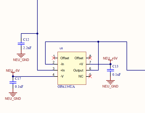
  1. OPAMP.png
  2. Can we give 5.8V to 3rd Pin?

      2. What would be  the output voltage at Pin 6? We are getting 4.3V but do not understand how it is coming?

Please clarify.

  • Hi Shiv,

    The input signal of an op amp cannot exceed the power supplies of the op amp. In addition, a 5.8V input signal would violate the input common mode range of the device. The VCM range of the OPA134 is (V-) + 2.5V <VCM < (V+) - 3.5V. For a ±5V supply, the VCM range would be -2.5V < VCM < 1.5V. Therefore, the maximum positive input signal on IN+ would be 1.5V.

    Likely, you are measuring 4.3V at the output because you are operating in a nonlinear state. A simple solution here would be to increase the voltage supply of the OPA134UA to ±15V. Since the circuit is in a buffer configuration, the output should match the input signal of 5.8V.

    Please let me know if you have further questions.

    Best regards,
    Carrie

  • Hello Carrie,

    Earlier we were supplying +/- 7V to the IC and Input side voltage at PIN 3 was 5.9V, So we are getting the same voltage at the output 5.9V but recently we made changes to the supply voltage to +/- 5V to IC and as I mentioned we are getting output voltage around 4.3V.

    I want to understand can we keep continuing giving 5.9V at the input side with IC voltage +/-5V having condition that 4.3V output we will get always? Is there any risk of damage or any issue?

    Also If we want to keep the same IC voltage +5/-5V then what is the input voltage we need to apply to get the same output voltage?

    Regards,

    Shiv

  • Hi Shiv,

    We do not recommend keeping the op amp in a nonlinear state. In this state, the behavior of the amplifier is unreliable, so the 4.3V output you are seeing cannot be guaranteed to be repeatable. In your current setup, the input voltage is 0.9V higher than the the supply. This setup puts the op amp beyond the absolute maximum ratings, which can cause damage to the amplifier (see below).

    If you would like to keep the same IC voltage at ±5V, I recommend setting the input signal between -2.5V < VCM < 1.5V. This allows the amplifier to operate in a linear state, and the output should also reflect the input signal.

    Please let me know if you have further questions.

    Best regards,
    Carrie

  • The VCM range of the OPA134 is (V-) + 2.5V <VCM < (V+) - 3.5V. For a ±7V supply, the VCM range would be -4.5V < VCM < 3.5V. Therefore, the maximum positive input signal on IN+ would be 3.5V but in actual for ±7V supply, we were applying 5.8V to the positive input signal on IN+ and getting the same 5.8V to the output signal. This circuit we were using from longer time with ±7V supply but never faced any issue. 

    This time we are reaching out as we changed the Supply voltage to ±5V. Please let me know is there any risk in applying 5.8V to input signal for ±7V supply?

  • Hi Shiv,

    The reason why you are seeing the 5.8V signal on the output is due to the input common mode range being violated. It seems like the output is swinging to the positive rail, which is 1.2V from V+. In this case, the output would swing to 5.8V on a 7V supply.

    We generally do not recommend designing circuits around the nonlinear behavior of the op amp. If you would like to keep the input signal at 5.8V, I recommend further increasing the supplies, perhaps to ±10V, such that the input common mode range and output swing of the amplifier is not being violated.

    Best,
    Carrie

  • Hello Carie,

    The output is not swinging for 7V supply, we are giving input 5.8V and getting the same 5.8V output everytime. I know here common mode range condition is not meeting and we should give 3.5V to the input. But we are using this circuit from longer time and getting 5.8V output everytime with 5.8V input for 7V supply.

  • Hi Shiv,

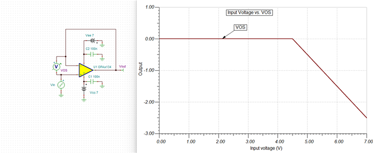
    I think there are two different interactions at play here. Although the input common mode may be violated, the op amp won't be damaged, but you will increase the error of the device. For example, the VOS will drastically increase as you exceed the common mode range (see simulation example below where the difference between the input and output voltages increase).

    Even though the maximum input common mode range is 3.5V (for a 7V supply), the output seems to behaving in a linear manner, reading 5.8V. However, the output also a limitation of 1.2V from the rail typically. It's possible the amplifier was reaching the upper output swing limitation of 5.8V, which in turn looks like the amplifier behaving in a linear manner.

    How are you measuring the IN+ signal? Are you basing this measurement off the input signal itself, or do you have a probe on IN+? Can you send me a screenshot of both the IN+ and OUT node in your current setup? 

    Best,
    Carrie

  • Hello Carrie,

    We are measuring the Input and output voltage with multimeter. At Input we have Zener and Diode combination circuit that will make voltage to Input signal to 5.8V.

    We are Planning to increase IC voltage rail to +/- 9V so that we can CM voltage range should be -6.5V < VCM < 5.5V and we are giving 5.8V input that I think should be fine with minor deviation from CM voltage range,

  • Hi Shiv,

    If you increase the supply voltage to +/-9V, then the output should still saturate at 5.5V (see simulation below).

    However, if you increase the supply voltage to +/-10, then the input voltage will match the output voltage (see below).

    If 5.5V is an acceptable output voltage for your application, then you can keep the changes you mentioned above. Otherwise, I recommend increasing the supplies to +/-10V.

    Please let me know if you have further questions.

    Best,
    Carrie