This thread has been locked.

If you have a related question, please click the "Ask a related question" button in the top right corner. The newly created question will be automatically linked to this question.

Using tlv320DAC3120 with a Stellaris


Hello,

I'm having quite a hard time trying to make it work. And there is not much documentation on using the board without a computer.

I supply power through the W5 test wire, 5v from the Stellaris board. Everything seems to be powered properly. I write the DAC registers using I2c, and this seems to work too (I read the registers with the control software, and their are changed accordingly to what I did).

I have a MCLK of 6MHz generated automaticaly (?!?). And it is 12Mhz when usb is plugged. Can I use this 6Mhz to clock the DAC? (I can also provide another clock on GPIO1 from the Stellaris).

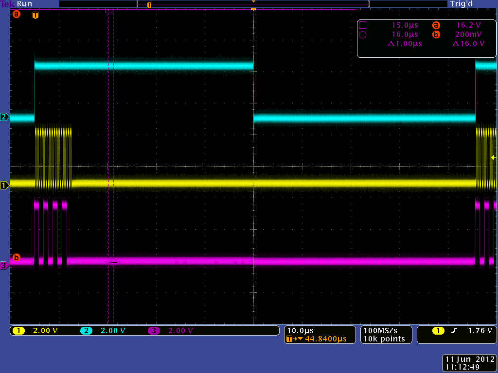
I send SPI data with the Stellaris, and check them on a scope, their are correct. But when I plug them on the DAC, they drop from 3.3 to about 1v. (BCLK, WCLK and DIN are configured as inputs)

Ideas? Comments? Examples?

Fabien

  • Fabien,

     You will have to lift the pins of TAS controller audio lines (BCLK, WCLK, DIN, DOUT - Called I2S data and not SPI) and MCLK if you want to provide them externally.

    Right now what you are seeing is a bus contention since TAS controller on EVM as well as the Stellaris board is trying to drive those lines.

  • Thank you for the answer. This is what we though after spending some time on the schematic...

    Maybe pulling the reset pin of TAS controller to ground will be enough. I'll try this before trashing the board completely.

    I also configured the DAC for a left justified audio stream, that is why I talked about SPI. I hope this is a proper way to do it. We'll see.

    I come back soon to validate your answer.

    Fabien

  • Ok, I have proper signals now.

    Wiring reset to groung is not enough. I removed the USB chip completely.

    Thank you!

  • Hello,

    I have another problem with this DAC. I can write and read registers now (That way I can check the writings). I configured the DAC to use it with the Stellaris, but I don't have the kind of audio output I expect. I think it's a problem with the digital audio signals.

    I use a timer on the Stellaris, at 44.1kH, and I use a SPI communication. Data mode on the DAC is configured to be left-justified.

    This is the digital audio outputs from the Stellaris:

    First is WCLK, second is BCLK and third is DIN.

     I am sending 0xCCCC (DIN). This seems to be exactly what the DAC is looking for.... but the output is still 0v.

    When I mess around with WCLK, sending just a pulse, and DIN, sending a sweep, for example, the DAC outputs a regular signal at the sweep's frequency, but the signal is non-sense. That means the clock is well configured, isn't it?

    This is the registers configuration:

    // select page 0
    WriteDACRegister(0x00, 0x00);
    // reset the DAC
    WriteDACRegister(0x01, 0x01);
    ROM_SysCtlDelay(SysCtlClockGet()*2/1000); // wait 2 ms change anything??
    // select page 0
    WriteDACRegister(0x00, 0x00);
    // PLL_CLKIN=MCLK, CODEC_CLKIN=PLL_CLK 1011
    WriteDACRegister(0x04, 0x03);
    ROM_SysCtlDelay(SysCtlClockGet()/10);
    tempDAC=ReadDACRegister(0x04);
    // PLL=on P=1 R=1 1001 0001
    WriteDACRegister(0x05, 0x91);
    ROM_SysCtlDelay(SysCtlClockGet()/10);
    tempDAC=ReadDACRegister(0x05);
    // J=8 00 1000
    WriteDACRegister(0x06, 0x08);
    // D = 4672 (01 0010)b=0x12 (0100 0000)b=0x40
    WriteDACRegister(0x07, 0x12);
    WriteDACRegister(0x08, 0x40);
    // mode is left-justified,wordlength is 16
    WriteDACRegister(0x1b, 0xC0);
    // NDAC=3
    WriteDACRegister(0x0b, 0x83);
    // MDAC=5
    WriteDACRegister(0x0c, 0x85);
    // DOSR=128
    WriteDACRegister(0x0d, 0x00);
    WriteDACRegister(0x0e, 0x80);
    // DAC => volume control thru pin disable
    WriteDACRegister(0x74, 0x00);
    // DAC => drc disable, th and hy
    WriteDACRegister(0x44, 0x00);
    // DAC => 0 db gain left
    WriteDACRegister(0x41, 0x00);
    WriteDACRegister(0x42, 0x00);
    // select page 1
    WriteDACRegister(0x00, 0x01);
    // De-pop, Power on = 800 ms, Step time = 4 ms
    WriteDACRegister(0x21, 0x4e);
    // HPL
    WriteDACRegister(0x1f, 0x82);
    // LDAC routed to HPL
    //WriteDACRegister(0x23, 0x40);
    // LDAC routed directly to HPL HPOUT
    WriteDACRegister(0x23, 0x80);
    // HPL unmute and gain 1db
    WriteDACRegister(0x28, 0x0e);
    WriteDACRegister(0x29, 0x0e);
    // No attenuation on HP
    WriteDACRegister(0x24, 0x00);
    WriteDACRegister(0x25, 0x00);
    //MIC BIAS = AVDD
    WriteDACRegister(0x2e, 0x0b);
    // MICPGA P = MIC 10k
    WriteDACRegister(0x30, 0x40);
    //MICPGA M - CM 10k
    WriteDACRegister(0x31, 0x40);
    // select page 0
    WriteDACRegister(0x00, 0x00);
    // select DAC DSP mode 11 & enable adaptive filter
    WriteDACRegister(0x3c, 0x0b);
    WriteDACRegister(0x00, 0x08);
    WriteDACRegister(0x01, 0x04);
    // select page 1
    WriteDACRegister(0x00, 0x01);
    // Unmute Class-D Left
    WriteDACRegister(0x2a, 0x1c);
    // Power-up Class-D drivers
    WriteDACRegister(0x20, 0xc6);
    // select page 0
    WriteDACRegister(0x00, 0x00);
    // POWERUP DAC (soft step disable)
    WriteDACRegister(0x3f, 0xd6);
    // UNMUTE DAC
    WriteDACRegister(0x40, 0x00);

    Can someone help me out?

    Thank you.

  • And I have a 10MHz clock on MCLK.

  • Fabien,

     Use the attached script as a reference (PLL configured for 48KHz sampling rate). Has both recording and playback enabled. 

    Assumes the device is I2S slave, i.e BCLK and WCLK is provided by the processor

    ###############################################
    # Software Reset
    ###############################################
    #
    # Select Page 0
    w 30 00 00
    #
    # Initialize the device through software reset
    w 30 01 01
    #
    ###############################################
    
    ###############################################
    # Clock and Interface Settings
    # ---------------------------------------------
    # The codec receives: MCLK = 10 MHz,
    # BLCK = 1.536 MHz, WCLK = 48.00 kHz
    ###############################################
    #
    # Select Page 0
    w 30 00 00
    #
    # PLL_clkin = MCLK, codec_clkin = PLL_CLK,
    # PLL on, P=1, R=1, J=9, D=8304
    w 30 04 03 91 09 20 70
    #
    # NDAC = 2, MDAC = 8, dividers powered on
    w 30 0b 82 88
    #
    # DOSR = 128
    w 30 0D 00 80
    #
    # NADC = 2, MADC = 8, dividers are powered down
    w 30 12 02 08
    #
    # AOSR = 128
    w 30 14 80
    #
    ###############################################
    
    ###############################################
    # Signal Processing Settings
    ###############################################
    #
    # Select Page 0
    w 30 00 00
    #
    # PRB_P1, PRB_R4
    w 30 3c 01 04
    #
    ###############################################
    
    ##########################################
    # Configure ADC Channel
    ##########################################
    #
    # Switch to Page 1
    w 30 00 01
    #
    # Programmed MICBIAS always on, 2.5V
    w 30 2E 0A
    #
    # MICPGA P = MIC1LP 20kohm
    w 30 30 80
    #
    # MICPGA M - CM 20kohm
    w 30 31 80
    #
    # PGA 0dB
    w 30 2f 00
    #
    # Switch to Page 0
    w 30 00 00
    #
    # POWERUP ADC channel, UNMUTE
    w 30 51 80 00
    #
    ##########################################
    
    ##########################################
    # Configure HP Output
    ##########################################
    #
    # Switch to Page 1
    w 30 00 01
    #
    # De-pop, Power on = 1.22s, Step time = 3.9 ms
    w 30 21 4e
    #
    # Route HP Analog Volume Control, 0dB
    w 30 24 80
    #
    # HP powerup, current limit, CM = 1.35V
    w 30 1f 94
    #
    # HP unmute and gain 0db
    w 30 28 06
    #
    ##########################################
    
    ##########################################
    # Configure DAC Channel
    ##########################################
    #
    # Switch to Page 1
    w 30 00 01
    #
    # DACs routed to Mixer Amplifiers
    w 30 23 40
    #
    # Switch to Page 0
    w 30 00 00
    #
    # Powerup DACs
    w 30 3f 94
    #
    # Unmute DACs, 0dB
    w 30 40 00 00 00
    #


  • Hello Vins,

    Thank you for the script. I tried, but it didn't worked. I had to find another solution for planning reasons. Too bad the evaluation module is so complicated to use without the USB...