


Hi,
We are using the TLV320AIC3254 DAC for testing the wav file given.We sees the strange thing happening in the DAC input and the output side.
BCLK = 3.072Mhz
WCLK = 48KHz
I2S Right justified 16 bit word
Scenario 1:
Input sample of 1KHz 16 bit - In output of the DAC we see the positive drip and noise is added in the output sample in osicilloscope
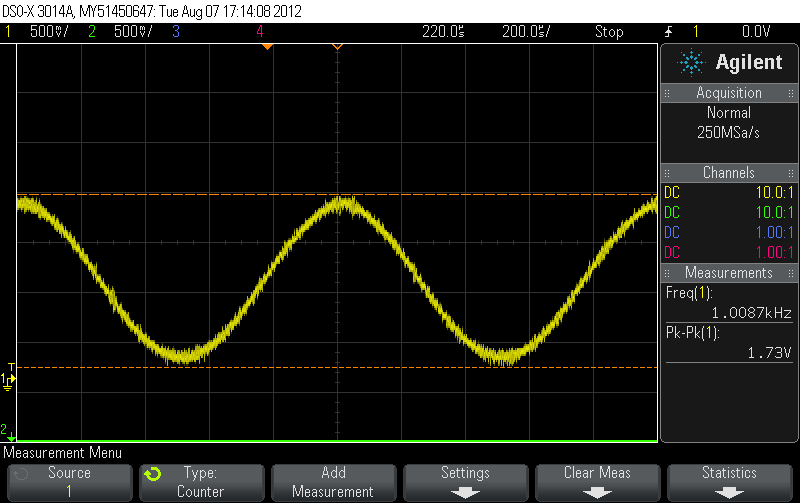
Scenario 2:
Input sample of 10KHz 16 bit - In output of the DAC noise is added and frequency is reduced to 400HZ in osicilloscope.
Input sample from above 6KHz we are seeing the output sample frequency reducing.When this kind of strange behavior will be aloowed in thw DAC.
Is there any configuration and CLOCK related stuff needs to be changed ?????
DAC Configuration - Registers
|
Page 0 Registers |
||||
|
1 |
Software Reset Register |
1 (0x01) |
0x01 |
Self clearing software reset |
|
2 |
Clock-Gen Muxing |
4 (0x04) |
0x01 |
Clock Source is selected as BCLK pin is CODEC_CLKIN, where BCLK is 3.072MHz. |
|
3 |
NDAC_VAL |
11 (0x0b) |
0x81 |
NDAC divider is powered up. DAC divider NDAC = 1 |
|
4 |
MDAC_VAL |
12 (0x0c) |
0x81 |
MDAC divider is powered up. DAC divider MDAC = 1 |
|
5 |
DAC OSR_MSB_VAL |
13 (0x0d) |
0x00 |
|
|
6 |
DAC OSR_LSB_VAL |
14 (0x0e) |
0x40 |
DAC OSR DOSR = 64 |
|
7 |
ADC Interface Setting1 |
27 (0x1b) |
0x00 |
Audio Interface = I2S, |
|
8 |
DAC Signal Processing Block Control Register |
60 (0x3c) |
0x01 |
DAC Signal Processing Block Defualt block is PRB_P1 |
|
9 |
DAC Channel Setup Register 1 |
63 (0x3f) |
0xD4 |
Both Left and Right channel DAC are powered up, |
|
10 |
DAC Channel Setup Register 2 |
64 (0x40) |
0x00 |
When Right DAC Channel is powered down, the data is zero, |
|
11 |
Left DAC Channel Digital Volume Control Register |
65 (0x41) |
0x00 |
Left Digital Volume Control = 0db |
|
12 |
Right DAC Channel Digital Volume Control Register |
66 (0x42) |
0x00 |
Right Digital Volume Control = 0dB |
|
Page 1 Registers |
||||
|
1 |
Power Configuration Register |
1 (0x01) |
0x08 |
Disabled weak connection of AVDD with DVDD. |
|
2 |
LDO Control Register |
2 (0x02) |
0x01 |
AVDD LDO Powered up. |
|
3 |
Playback Configuration Register 1 |
3 (0x03) |
0x00 |
Left DAC in mode PTM_P3, PTM_P4 |
|
4 |
Playback Configuration Register 2 |
4 (0x04) |
0x00 |
Right DAC in mode PTM_P3, PTM_P4 |
|
5 |
Output Driver Power Control Register |
9 (0x09) |
0x30 |
HPR is powered up, |
|
6 |
Common Mode Control Register |
10 (0x0a) |
0x00 |
Output of HPL & HPR is powered with AVDD supply, |
|
8 |
HPL Routing Selection Register |
12 (0x0c) |
0x08 |
Left Channel DAC reconstruction filter's positive terminal is routed to HPL. |
|
9 |
HPR Routing Selection Register |
13 (0x0d) |
0x08 |
Right Channel DAC reconstruction filter's positive terminal is routed to HPR. |
|
10 |
HPL Driver Gain Setting Register |
16 (0x10) |
0x00 |
HPL driver gain is 0dB |
|
11 |
HPR Driver Gain Setting Register |
17(0x11) |
0x00 |
HPR driver gain is 0dB |
|
12 |
Headphone Driver Startup Control Register |
20 (0x14) |
0x00 |
Soft routing step time is 0ms, |
|
13 |
Reference Power-up Configuration Register |
123 (0x7b) |
0x01 |
Reference will power up in 40ms when analog blocks are powered up |