This thread has been locked.

If you have a related question, please click the "Ask a related question" button in the top right corner. The newly created question will be automatically linked to this question.

PCM2906C Digital Input not working

Other Parts Discussed in Thread: PCM2906C, PCM2906CEVM-U, PCM2902, PCM2900C, PCM2900, SN74LVC1T45, PCM2903, PCM2903EVM-U, PCM2903C

Hello,

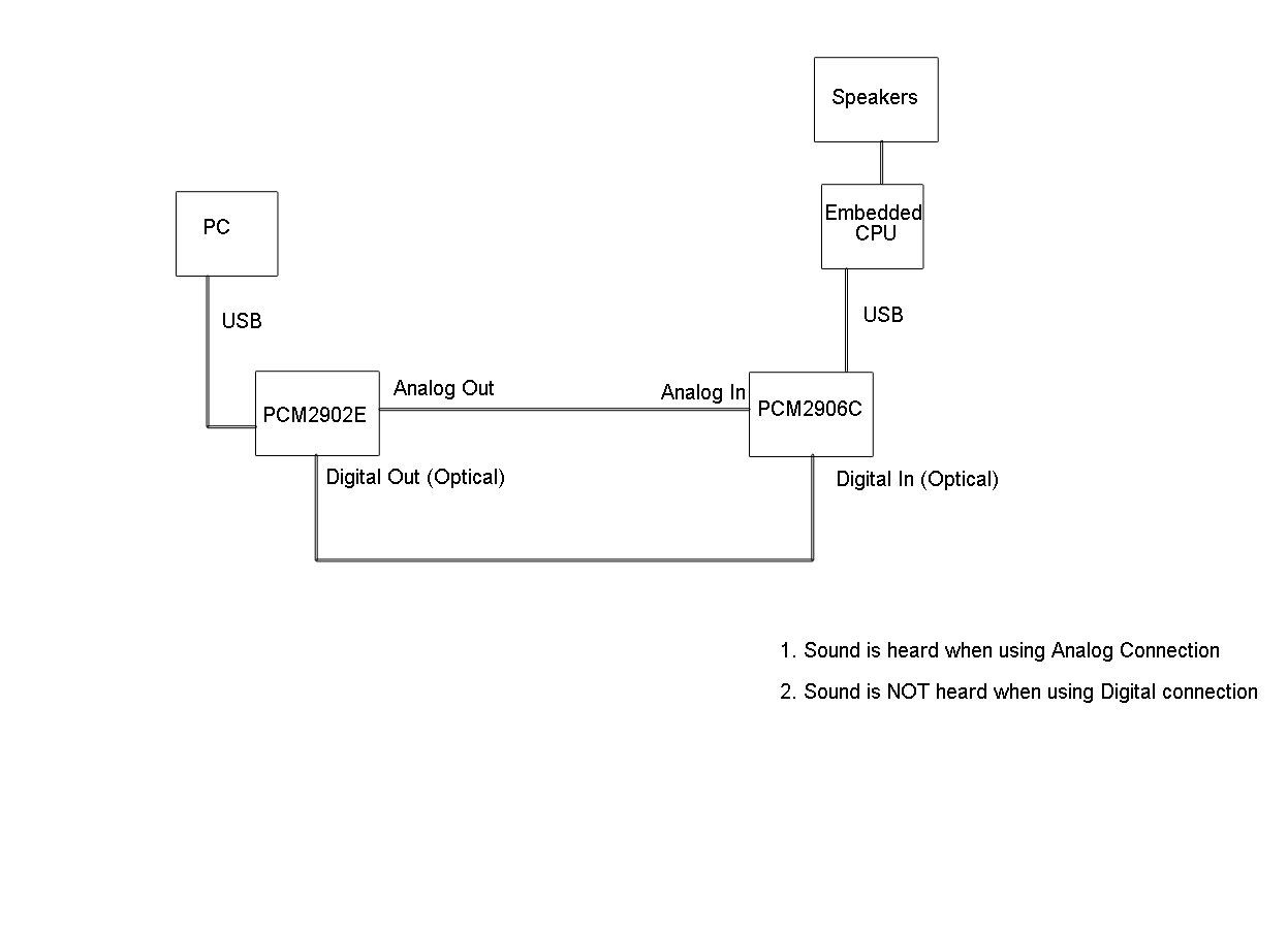
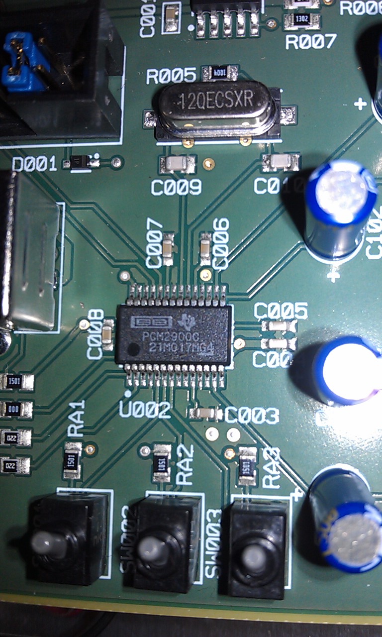
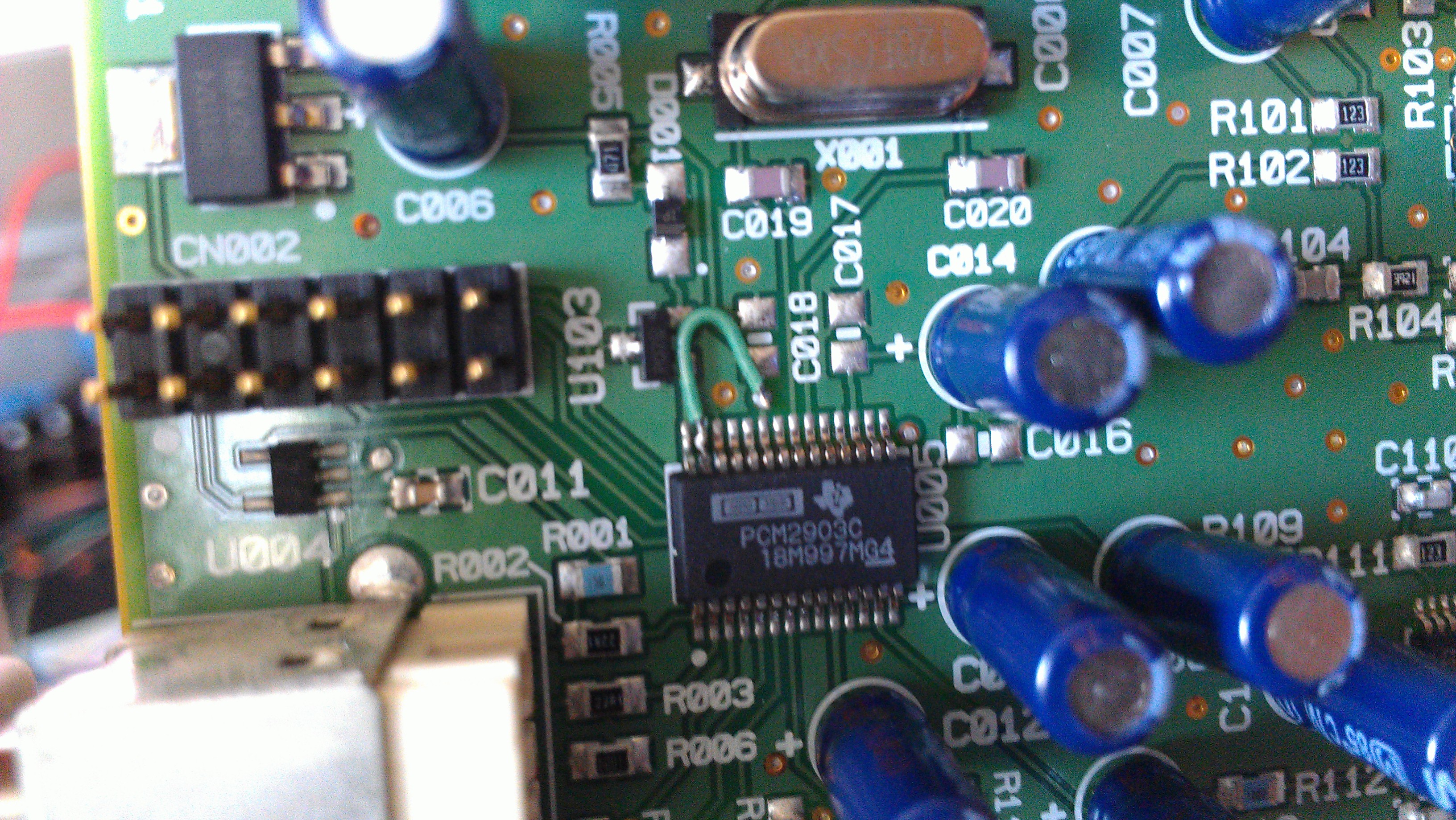
I have a design using the PCM2906C which implements only the Line In and the Digital In S/PDIF via an optical receiver.

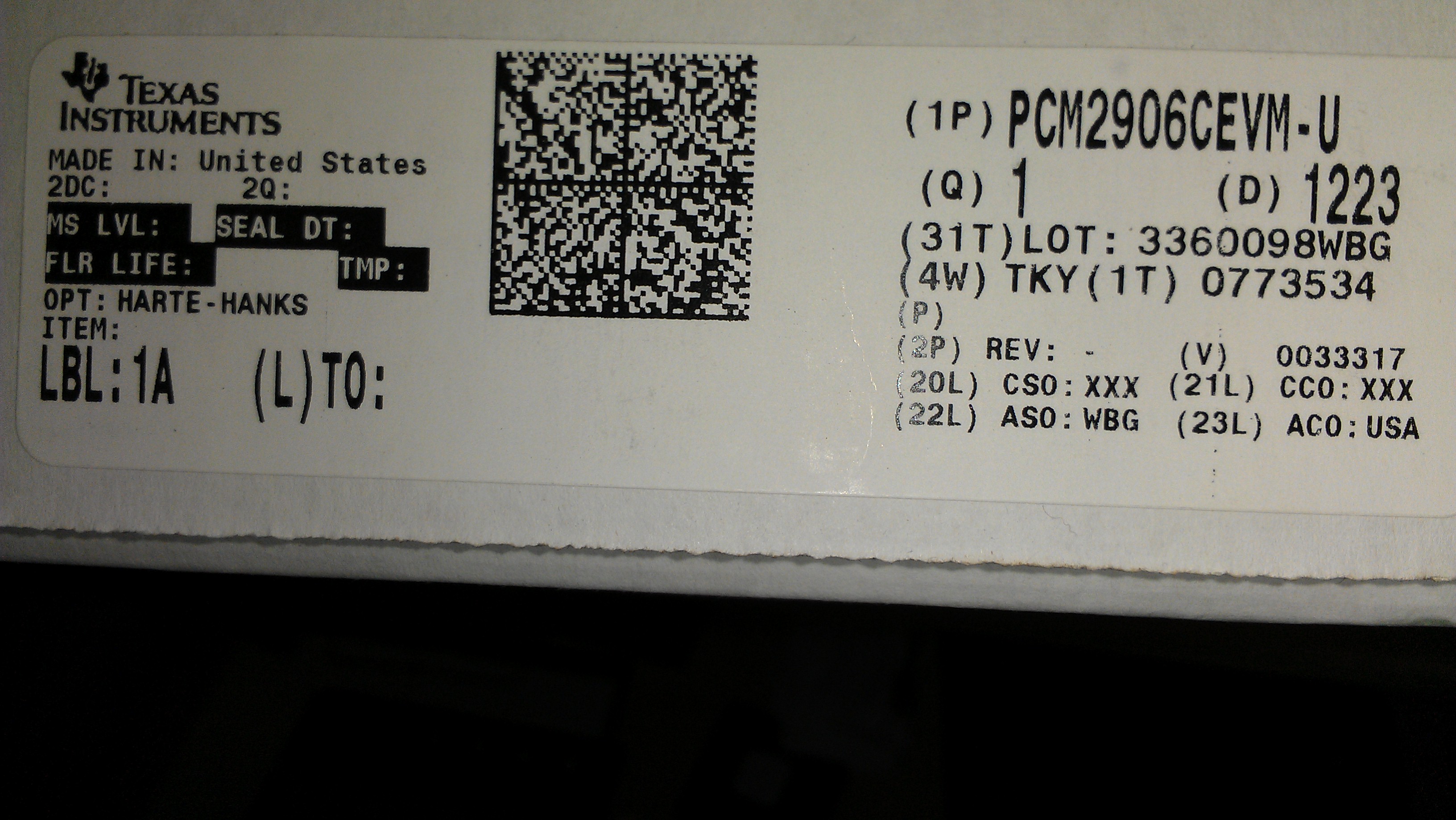
The PCM2906CEVM-U did not contain any connectors for the S/PDIF so I had contacted TI support via email and it was suggested that I reference the PCM2903CEVM-U schematic for the Optical Input.


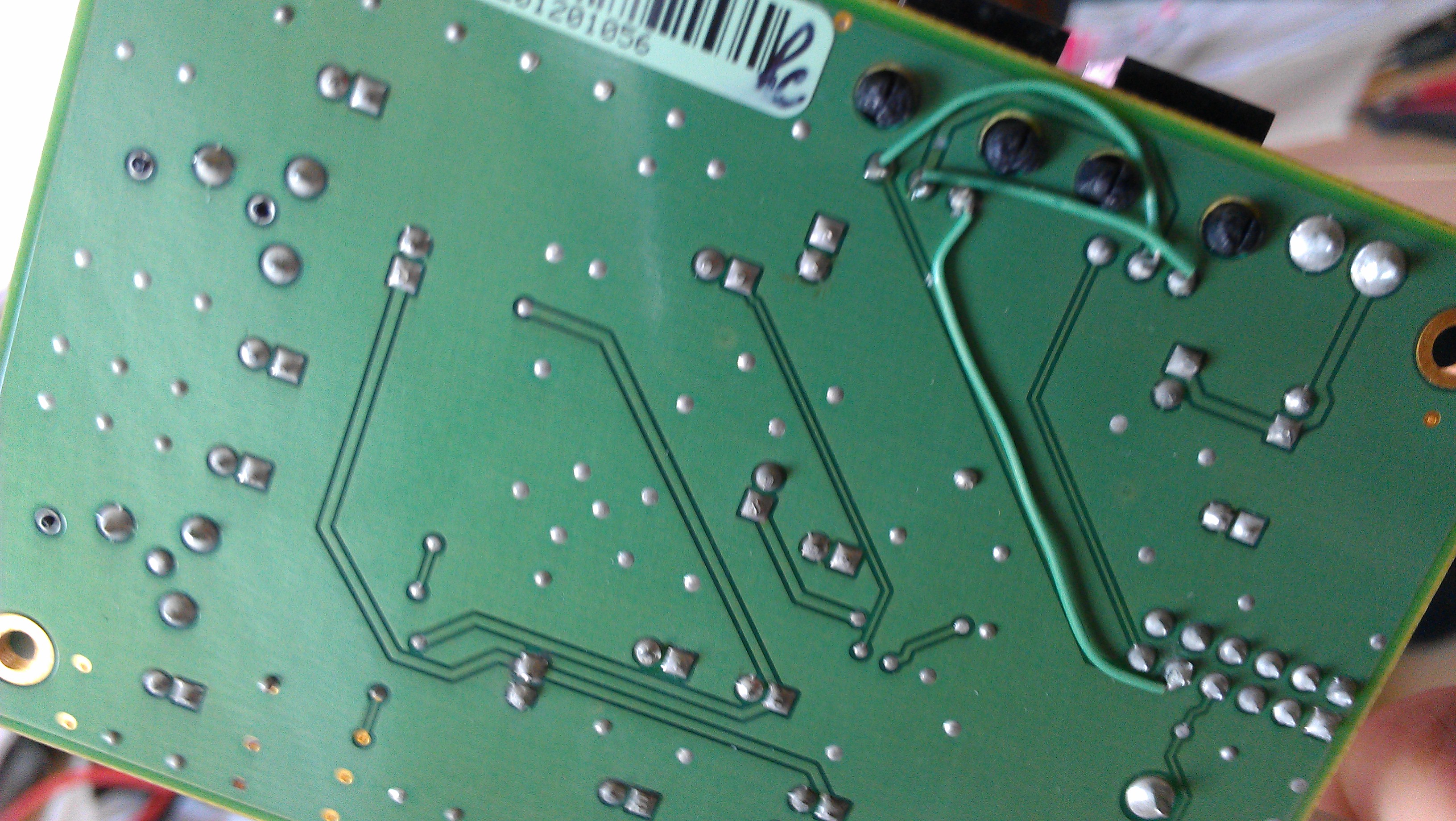
The PCM2903CEVM-U used part TORX177L for the Optical Receiver which is now EOL so I have used Everlight PLR135/T9 which was listed on Digi-Key as a substitute. 

Datasheet:

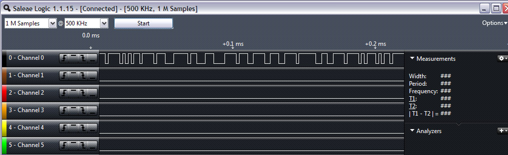
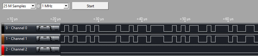
However, I can't seem to get the Digital Input working. There are oscillations on the output from the Optical Receiver when audio is played indicating the receiver is working but the PCM2906C does not relay anything to the host. The audio being played is a YouTube video from a PC with optical out.

There is no indication on the host side that the digital input port is detected.  Is there something I need to do to enable the DIN? Is there some driver configuration required to enable the DIN?

From what I understand from the PCM2906C datasheet is that it should automatically detect data on the DIN and switch over, but seems like this is not happening. 

Thanks in advance for the help!
  • I found this post concerning the PCM2906 and the Digital Input:
    http://e2e.ti.com/support/data_converters/audio_converters/f/64/t/204457.aspx

    Could this be an issue?


    UPDATE: I have also tried playing audio from an Xbox with the same issue. The audio is not transferred to the host.

  • I'm not totally convinced the issue I have is due to the copyright bit.

    I got my hands on a Behringer UCA202 which uses the PCM2902E and provides an optical out. In the PCM2902 and the PCM2906 datasheet it is mentioned that "Digital audio data output is always encoded as original with SCMS control."

    So my interpretation of this was that if we played any audio out of the PCM2902E optical out and fed it to the optical in of the PCM2906C then there should be no problems. However I have the same issue with this setup. I see oscillations from the optical receiver output but no audio is being sent by the PCM2906C to it's host.

    Any help is greatly appreciated!
  • Hi, Omair,

    Sorry for the delay in getting back to you.

    The copyright stuff determines whether you can get digital out or only analog out.

    Do you have output on the analog out?

    -d2

  • Hi Don,

    Thanks for the reply.

    I'm a little confused, do you mean input instead of output? If so then analog input is working fine. 

    We have not implemented either of the outputs (Digital or Analog) on the new PCM2906 design since these functions are not required for the device we are building.

    If you are referring to the output on the PCM2902 which I was using to testing the PCM2906 inputs with then yes, the PCM2902 analog output works and the PCM2906 is able to send the audio to its host. But nothing happens when trying to use the PCM2902 digital output and PCM2906 digital input. (See attached setup diagram)


    Thanks 


  • Also, attached is a scope output of the PCM2906C Digital In pin.

    It does look like the PCM2902 Digital Output is working and the Optical receiver on the PCM2906C is sending it data, but the PCM2906C is not sending it to the host. 

    Thanks

  • I think I may have found a reason why the optical is not working even for devices we believe not to have the copyright bit. 

    I was going over the datasheets again and found a discrepancy in the optical connector. They are outputting only 2.1V - 2.5V for a high bit (Voh) whereas the audio codec chips are looking for 2.52V - 5.52V to register a high bit. So it looks like the chip never recognizes there is any data coming through because to it, everything appears like a 0.

    This is strange because the connector we used is listed as a direct drop in replacement for the one used in the reference design. The one used in the reference design is EOL but has a Voh of 4.8V (this is the only apparent difference by looking at the datasheets). 

    Even stranger is that all the newer optical connectors have a Voh of 2.5V and pretty much all of the older generation connectors which used to output 4.8V are now EOL. I have only found 2 which are still available and they have extremely high MOQs of 5000pcs. If the connector trend is going towards only providing 2.5V as a high logic level, perhaps TI should consider revising the Vih threshold for the digital input to something like 2V - 5.52V.

    I'm thinking about using the SN74LVC1T45 level shifter with the following configuration to get around this issue:

    Dir = 3.3V (direction A to B)
    VccA = 3.3V
    VccB = 5V 
    A connected to output of optical receiver
    B connected to PCM2906C digital input

    According to Pg 4 of the datasheet, if Vcci (VccA in our case) is 3V-3.6V then Vih min is 2V so this should be good to detect the high level from the optical receiver between the range of 2.1V-2.5V.

    Also, according to Pg 5, if Vcco (VccB in our case) is 4.5V then Voh min is 3.8V so it should be a little higher for VccB = 5V. This is in the 2.52V - 5.52V range for Vih of PCM2906.

    I'm thinking the switching times should be sufficient since the datasheet is quoting the divice can perform 75Mbps - 420Mbps.
  • Omair,

    Looking at your drawing, I think the copyright bit is going to be a problem... Have you put a scope on the DOUT to see if it's actually driving anything into the optical jack?

    -d2

  • You are going well beyond what I'm trying to do. All I want is to be able to feed coaxial SPDIF to the chip and from the chip, no optical involved. I'm led to believe that there are three differing SPDIF interfaces: TTL, Coax, and TOSLINK (Optical). Perhaps I need a circuit to change the levels at the chip, such as the ones described here:

    http://sound.westhost.com/p85-f5a.gif

    http://sound.westhost.com/p85-f6.gif

    Any thought before I give it a go?

  • Hi William,

    Yes, you are correct for a coaxial you would definitely need circuits similar to ones you linked to above.

    The TOSLINK connectors are meant to provide a TTL output also. The connectors essentially have circuitry inside which converts the optical signal to a TTL signal.

    The first generation connectors operated at 5V (meaning the output for a high bit was 4.8V). However the new generation connectors are only outputting 2.50V for a high bit. Technically, anything between 2V - 5V is a valid high bit for TTL(http://www.allaboutcircuits.com/vol_4/chpt_3/10.html), however, the PCM2906C will not register a high bit if the voltage is lower than than 2.52V.

  • Does anyone have any more information with respect to the S/PDIF in and out on the PCM2906C chip? I can't seem to get anything to register on my scope other than background noise. I've got the EVM board plugged into a Windows box, the Windows box playing back a sine wave. I can hear the audio via the analog outputs on the EVM, but the DOut pin doesn't seem to be doing anything. I see maybe 5 mV on the scope, which doesn't change significantly when I remove the USB cable from the EVM board.

    There's not much else I can try at this point. I haven't even begun building TTL to Coax converters, since I don't have any signal to work with. Is there a setting / driver / jumper that needs to be set differently that I just have not stumbled on yet?

  • I just tested out the DOUT pin on my PCM2906CEVM and got the same result as you. Upon further investigation it appears that the chip on the EVM is actually the PCM2900C which DOES NOT support S/PDIF (even though the board I ordered was the PCM2906CEVM). 

    Is it the same case with your EVM?

    Looks like TI made a single PCB for the PCM2900CEVM, PCM2902CEVM, and PCM2906CEVM but only sending out boards populated with the PCM2900C.


    Unfortunately I have not routed out the DOUT pin on our  custom PCB as indicated earlier so I am unable to report what an actual PCM2906C chip's DOUT is doing.

    If your board is the same as mine and contains a PCM2900C instead of a PCM2906C, my recommendation would be that if you are able to, just order a PCM2906C from DigiKey and replace the chip on the EVM. Or, contact TI to tell them the EVM you received contains a PCM2900C instead of the PCM2906C which you ordered and to send you a replacement.

  • Omair,

    Interesting... It seems like our board shop may have made a mistake.

    Don't bother ordering a replacement EVM... You will get the same thing. What's the definition of insanity?

    I will look into this to see what happened and fix it. You can order a sample and replace it yourself, or if you'd like, you can send it to me, and I can get it fixed for you. I am pretty slow at soldering, though. :)

    You don't need to buy it from Digikey, you should be able to order a free sample IC from our website unless we're stocked out at the moment.

    -d2

  • Omair,

    What does the sticker on the ESD bag the EVM came in say?

    -d2

  • Hi D2,

    Sticker on ESD bag says 6530373.

    Also, attached is a snapshot of the sticker on the box.

    Thanks


  • Omair,

    Thanks. My notebook is in the shop, and I can't VPN in from my home machine, so when I get to work tomorrow, I will look all this up and see if I can figure out what went wrong.

    I also ordered one myself to see what I get when it turns up! 

    We use one vendor to build and test the boards, and a second vendor to put them in the boxes (how's that for specialization). We could have given confusing instructions to either one that resulted in the mix-up.

    -d2 

  • You can include me in this exchange. Checking the chip this morning it is indeed a PCM2900, not a PCM2906. Picture of bag label and box label attached.

    Where should I send it to get the correct chip placed on the board?

  • Hi, Guys,

    I received the one I ordered from our distribution center, and I too received the PCM2900C IC instead of the PCM2906C.

    We are in the process of re-working our inventory to get this fixed.

    If you'd like to get your EVMs replaced, please contact the channel from which you got the EVM.

    -d2

  • I have been working with the TI support team member Naser VIA email on this issue but I just got a generic reply from the support ticket system stating that all support is being migrated here so I am posting my query here hoping that he is on here as well now and can reply since he knows this issue well....

    We modified our design to create a level shifter for the SPDIF input using the SN74LVC1T45 as we discussed (emails with TI support copied below). 

    However, the SN74LVC1T45 is not functioning as we thought it would based on the datasheet and the confirmation from the Logic Product group.

    I used a scope to make sure there is data going through (from A to B) but the output data voltage (B) is the same as the input data voltage (A) although VccA = 3.3V and VccB = 5V. It does not appear as though the SN74LVC1T45 is performing the level shift as we thought it would, but rather just passing the signal through at the same voltage that it is received.

    Any ideas why this might be happening?

    Thanks,
    -Omair


    On Tue, Dec 4, 2012 at 7:09 AM, <support@ti.com> wrote:

    HI Omair:

    I just confirmed with Logic product group. I don’t see anything wrong with the description below. It should work. Take care.


    Regards,

    Naser


    [THREAD ID:1-DM1MLG]


    On Mon, Dec 3, 2012 at 2:48 PM, <support@ti.com> wrote:

    HI Omair: Thanks for the reply. Yes, this sounds right and I think it will work. Let me do additional digging and discuss with the Logic product group and get back with you.

    Regards,

    Naser

    [THREAD ID:1-DM1MLG]

    -----Original Message----- 
    From: omair.khan
    Sent: 11/30/2012 01:30:47 PM
    To: support@ti.com
    Subject: Re: Re: Re: Re: Re: Re: Re: Re: Re: AAP, Email Technical Support, www.ti.com, PCM2906C

    Hi Naser,
    Thanks for the link.
    I'm thinking the SN74LVC1T45 might work with the following configuration:

    Dir = 3.3V (direction A to B)
    VccA = 3.3V
    VccB = 5V 
    A connected to output of optical receiver
    B connected to PCM2906C digital input
    According to Pg 4 of the datasheet, if Vcci (VccA in our case) is 3V-3.6V then Vih min is 2V so this should be good to detect the high level from the optical receiver between the range of 2.1V-2.5V.
    Also, according to Pg 5, if Vcco (VccB in our case) is 4.5V then Voh min is 3.8V so it should be a little higher for VccB = 5V. This is in the 2.52V - 5.52V range for Vih of PCM2906.
    I think the switching times should be sufficient for 16 bit, 44.1khz audio (which has a data rate of 1411.2Kbps) since the datasheet is quoting the translator can perform 75Mbps - 420Mbps.
    Does all this sound correct to you?
    Thanks,
    -Omair
  • Hi, Omair,

    Sorry for the run-around (pre and post)...

    The SN74LVC1T45 is supported by another group at TI. I looked at the d/s, and I would assume that it works like you assumed it would work, but obviously it only scales down, not up. I'm sure we have actual level translators that do what you want, but I am not very familiar with those devices.

    We do have a forum dedicated to logic devices - you might try there for more advice. Here is the link to their forum.

    -d2

  • Hi D2, thanks for the info. I've posted in the logic forum. hopefully someone can help there. 

    Thanks!

  • Hi D2,

    We have so far been unsuccessful in implementing SPDIF with the PCM2906. The voltage discrepancy is killing us. The PCM2906 is looking for a min 2.52V for a high bit, but all the connectors available only go up to 2.41V.

    I noticed the PCM2903 EVM is the only one that provides SPDIF connectors so I have purchased one to do some testing, however there are a few issues. Can you help?

    1) The PCM2903 EVM did not come with any jumpers installed on CN002. The EVM is not functioning without jumpers and the user manual does not provide the default jumper configuration. Can you please indicate which jumpers should be connected for normal operation?

    2) There appear to be a few cut traces and wire jumpers both on the top and bottom of the PCM2903 EVM. Is there a document which details which signals were re-routed to what? Does the schematic in the user manual show the correct connections (ie. the working configuration after jumper wires were added on the board) or is the schematic only reflecting the original connections (before the traces were cut and jumper wires added)?

    It also appears that the PCM2903 is not drop in replaceable with the PCM2906 so we would need to do some PCB modifications if the SPDIF works on the PCM2903 EVM.

    Thanks 

  • Omair,

    1)  All of the jumpers except the first one (to the left, closest to the edge of the board).  They allow for SEL pin configuration and DIN/DOUT routing.

    2)  This was a re-work to fix the SPDIF receiver.

  • Hi Patrick,

    Thanks for the reply. Can you please confirm if the schematic in the EVM User Manual is up-to-date and reflects this fix?

    Thanks

  • Hi Patrick,

    Also, I installed the jumpers how you suggested but the board is still not working. So I tested the 3.3V regulator, looks like it is receiving the 5V from the CN1 header but VOUT is 0V. Looks like the board has a defective regulator. How can I exchange the board? I purchased it from the TI E-Store.

    Thanks 

  • Hi Don / Patrick,

    I have received my replacement PCM2903EVM-U. The board is working fine, but unfortunately the SPDIF input on this is not functioning either.

    In fact, I am having a similar issue as to what I experienced with the PCM2906C; the Voh from the connector is not high enough for the PCM2903C to register anything is coming in on the DIN (SPDIF in). 

    According to the PCM2903C datasheet the Vih min for DIN is 0.7Vdd. I measured the regulator output at 3.28V so this means the Vih min should be 2.3V. However, the SPDIF connector is only outputting a max of 2.0V. 

    The issue was similar with the PCM2906C, the device was looking for Vih min of 2.52V but the connector I used in my design was outputting max of only 2.50V. Was the SPDIF input ever tested functionally on these PCMs? I'm starting to wonder if there is something internally in the PCM chips causing the output to drop below desired levels? 

  • Hi, Omair,

    Thanks for your post, and I apologize that you are still having trouble.

    We have been having a hard time finding the SPDIF transceivers, and I wonder if our vendor swapped them and the new ones don't provide a large enough output voltage.

    Since the EVMs we have in the office all work fine, let me order on from the eStore and test it. It will be mid-next week until we get results back to you.

    -d2

  • Hi D2,

    Thanks for the reply. 

    I experienced a similar issue when trying to obtain the Toshiba connectors originally used on the PCM2903EVM. It looks like they have been EOL for some time now so I wouldn't be surprised if these have been replaced on the EVM also.

    Let me know what you find out with the new board you ordered.

    Also, I tested out the connector I have been using in the PCM2906C design (PLR135/T10). The connector completely out of the circuit outputs 2.9V for a high bit. So I decided to disconnect the connector on the PCM2903EVM and replace it with this one and see what happens. There was a voltage drop in the output when connected to the connector was in-circuit. The high bit is only going up to 2.4V (vs 2.9V out of circuti). But unfortunately, even though the voltage is now above the estimated min of 2.3V with this connector, I am still not getting any of the audio through into the USB host.

    Below is a logic analyzer output: (Channel 0 is at the connector's Vout and Channel 1 is at the DIN pin of the PCM2903)

    So we know that there is something happening at the DIN pin. Maybe 2.4V is still too low for the chip? 

    What voltage level is the connector on the original boards you have in the office outputting for a high bit? I would just like to compare it to something that is known working.

    Thanks

  • Hi Omair,

    I think that the use case of SN74LVC1T45 by you may be not correct, try the circuits in below, which use B as the input, A as the output, VccA=5V, VccB=3.3V.

    Thanks!

  • Hi Omair,

    We have verified this on our EVM borad(PCM2903EVM-U), SPDIF input function works well without any problems, and the optical receiver output voltage amplitude is about 4Vp-p.

    Do you have any progress on this?

    Thanks!

  • Hi Jacky, 

    Thanks for the reply. I still have not been able to get the SPDIF on the PCM2903EVM to work. There is no audio being transferred to the USB host.

    Is the board you tested the original engineering board or the new one D2 ordered to test?

    Also, what is the source of your audio? 

    I'm getting another audio source with a SPDIF output so I will try with that and see what happens.

  • Hi Omair,

    The board i have tested is the new board that D2 applied for me, and the optical SPDIF audio source comes from Audio Precision.

     Yes, it will be better you that you can try another SPDIF audio source to see if the problem still exists, and also measure the output voltage of th optical receiver(in my test, the voltage is about 4Vp-p on DIN pin of PCM2903C).

    Thanks!

  • Hi Jacky,

    Ok, so I've tried with 3 SPDIF audio sources now:

    1) Laptop

    2) Xbox

    3) Behringer board which uses PCM2902E

    The voltage for the original connector on board is showing 4Vp-p (ie. 2V for high bit). 

    The voltage for the new connector I connected (PLR135/T10) is showing 5Vp-p (ie. 2.5V for high bit).

    But I still cannot get any audio from either of these 3 sources. 

  • Hi Jacky, 

    Ok I think I've figured out what's going on!

    The issue seems to be related to the drivers on the USB host.

    Our default test machine is Windows XP which the SPDIF is not working on (the Line in works fine but no audio over SPDIF).  Just out of luck I decided to try it on a new Windows 8 machine and voila! It worked as intended. I also tried on a Windows Vista machine and it works fine. So it appears the issue is related to the drivers in Windows XP and not the hardware. I also tried our custom boards we built using the PCM2906C and they are also working fine on the Windows 8 and Windows Vista machines. 

    Any idea on what we can do to get this working on Windows XP also? 

    The final application for this is going to be with an Embedded Linux as the host. Now that we know the hardware is working fine, our software guys will try to use SPDIF with the Embedded Linux. Hopefully there won't be any issues similar to the Windows XP issue. 

  • Hi Omair,

    By the way, do you know what's the sample rate of your SPDIF audio source, and have you set it as same as on the PC recorded software?

    Thanks.

  • Hi Jacky,

    The source is playing at 16bit, 44100 Hz. I am just using the Windows built in sound recorder software and did not find any option to set this anywhere. 

    As I mentioned earlier it looks like the SPDIF input functions fine on Windows Vista and Windows 8, but not on Windows XP.

  • Hi Omair,

    We have test it on winXP, it works fine but not use windows built in sound recorder, we use some others recorder software which can change the sample rate in the software. Attachment here is a free software which you can have a try, and we have tested it works well:

    http://audacity.sourceforge.net/download/?lang=zh-TW

    Thanks.

  • Hi Jacky,

    The SPDIF is working fine with Audacity on Windows XP. So looks like the problem was with the built in Sound Recorder software. 

    Thanks for all the help! It is very much appreciated.