This thread has been locked.

If you have a related question, please click the "Ask a related question" button in the top right corner. The newly created question will be automatically linked to this question.

I2S Bus and TLV320AIC3104

Other Parts Discussed in Thread: TLV320AIC3104


We are planning to use the Audio-codec TLV320AIC3104.The Audio-Codec constists of two DATA-Connections, one for Input, the other for Output. The I2S Standard particularized only one wire of DATA (In-and Output).
Can I connect the DATA-IN and DATA-OUT simply together ?? or that I  have to do to connect them "correct" to a µC, which supported only one DATA-Connection?

  • You cannot connect the I2S DIN and DOUT signals together and achieve independent operation of the ADC and the DAC. One is used to transfer digital audio data from the uC to the codec and the other one is used to transfer digital audio data from the codec to the uC.

    Please check, if you are mixing up I2S with I2C. The former is used for digital audio data and has dedicated signals for input and output. The latter is used for control and its standard (I2C) does call for a one wire connection for both directions (IN & OUT). The AIC3104 follows this standard (SDA used for both data in and data out) for the control I2C interface.


  • I have a question in regards to the Dout and Din that is somewhat related.


    I have the TI TLV3104 Evaluation board, and want to test the performance of the ADCs and DACs. How would I go about routing the data on Dout to Din so as to feedback the digital data to the codec to be played on the low power outputs.


    Thanks;

    Leo

  • You can place the AIC3104 in digital loop-back where the data from the ADC is looped digitally back to the DAC and played at the outputs. To do this you must first disable the USB I2S. Do this by moving the switch labeled "USB I2S" on SW-2 on the motherboard to the right. Next, place the AIC3104 into Master Mode by making BCLK and WCLK outputs using the GUI. Finally, put a jumper between DIN and DOUT on J14 on the motherboard. Now you can enable inputs, ADC, DAC, and outputs on the GUI and this will test your entire system.


  • Thanks for the response.


    I got this to work. The performance was much worse then I was expecting though.


    I am getting about -65 dB measuring Total Harmonic Distortion + Noise (THD+N).

    When i route the audio from the PGA directly to the outputs without using the ADC and DAC I get about -86 dB which is fine.

    This -65 dB value I am not really sure whose performance I am measuring the ADC or the DAC.

    We need the ADC to have at least -85 dB here.

    Can the 3104 even achieve such values?


    Thanks;

  • You should be able to get at least the min number specified in the Datasheet (-75dB) and typically much better (89 - 95 dB). there is likely something wrong with your configuration of the AIC3104 or the test setup you are using. If you want to elaborate on either, we can take a look and try to figure out what is going wrong...

  • I changed some stuff in the setup and am curretnly getting about  -75-76dB. I have an audio analyzer directly connected to the IN1L + and - inputs with the ground lead connected to G.

    I am monitoring the Left_Out low power output across a 10k 1% resistor.

    -75dB will not work for us do you have any codecs that are the same with better THD+N performance?

    Thanks.

  • Hi Leonid,


    Which audio analyzer are you using and what filtering are you using on the input of the analyzer?


    Thanks

  • I am using an audio precision audio analyzer.

    I have attached a picture with the setting of the audio analyzer.

  • If you are feeding the ADC single-ended, the input is too high. If you are differential, it is too low. We typically test at -2dBFS to have as high of a SNR without risk of clipping due to offset.


    Also, we typically use an input filter to limit out of band noise before it enters the AP. In your case, I can see the measurement is band limited to Fs/2 but unfortunately, this is after any out of band noise has been exposed to the front end of the AP which can effect the measurement. Please see:


    http://focus.ti.com/lit/an/slaa313/slaa313.pdf


  • I though that the full scale was 2Vpp which ends up being .707Vrms which is what I am putting into the codec with the analyzer. Is this for single ended or differential?

    If not when what is the level? The data sheet does not make this really clear.

  • The single ended full scale input range is .707 Vrms. The differential full scale input range is 1.414 Vrms. In either case, we use 2 dB below full scale when testing distortion (.561 Vrms single ended, 1.123 Vrms differential) to insure that there is no clipping due to offset. You should be seeing numbers in the 80's for THD+N. The only reason for the -75 dB min in the data sheet is the limitation of our production tester. On the AP, it should be better than what you are seeing. The issue could also be register settings in the AIC3104. I would be happy to look them over if you would like to post them.


  • I ran the test with a 20kHz LPF set on the audio analyzer and 1.123Vrm input and got -84dB. This is much better.


    What is weird, is that no matter whether I set the Codec to operate at 16Bits or 24bits the result is the same, i would think that the results should be better with the higher resolution?

  • Internally, the device always runs in 24 bit mode. The output is formated based on the register settings and since 16 bits should give us a theoretical 98 dB, you won't see much difference when switching to 24 bits. There is probably some benefit though if you are running DSP algorithms on the 24 bit data vs. 16.

  • Another thing is that the DAC noise will affect the ranging of the AP front-end, so you need a physical filter beforehand. You can use an AUX-0025 box from AP or an internal pre-analyzer filter from AP. See http://www.ap.com/products/accessories/aes17_filters.

    Also, you could use a simple RC filter with an fc ~33kHz.

    When using these filters, the DAC SNR should be around 100dBA in this part in 24-bit mode and a bit more than 96dB in 16-bit mode (due to A-weighting).

    Regards,

    J-


  • I have an AUX-0025. I will try measuring it with this filter.

    Thanks.

    Leonid

  • Hi


    Leonid Ayzenshtat said:

    I am getting about -65 dB measuring Total Harmonic Distortion + Noise (THD+N).

    When i route the audio from the PGA directly to the outputs without using the ADC and DAC I get about -86 dB which is fine.

    This -65 dB value I am not really sure whose performance I am measuring the ADC or the DAC.


    What did you change? i have the same problem.

  • Hi Converter Apps,

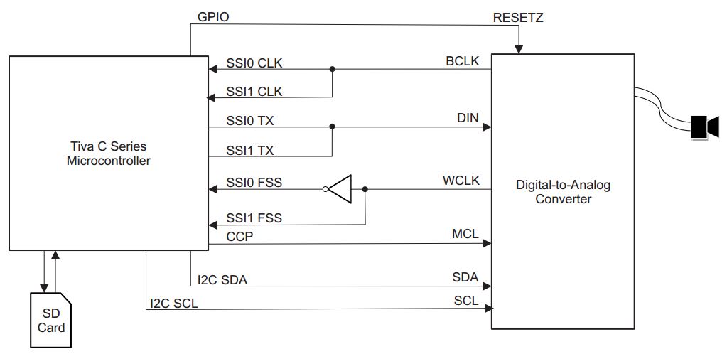
    I want to use the I2S to send data from the AIC3104 (ADC) to µC and then from µC to AIC3104 (DAC). In the picture below you can see how to send from µC to AIC3104. How do I have to connect the Pins, if I want to send data from AIC3104 to µC?

    Sadullah

  • Hi, Sadullah,

    The TLV320AIC3104 has a DOUT pin used to stream the digital data from the ADC to the microcontroller. The I²S bus would be the same for DOUT and DIN pins. Please refer to below basic diagram as reference.

    Best Regards,

      -Diego Meléndez López
       Audio Applications Engineer