This thread has been locked.

If you have a related question, please click the "Ask a related question" button in the top right corner. The newly created question will be automatically linked to this question.

how to parallel TPA3122D2 outputs to single speaker? and power-on pop avoidance

Other Parts Discussed in Thread: TPA3122D2, DRV134, OPA2132

My first question is merely about saving unecessary passive parts; the second is an actual problem:

1. Paralleled outputs:

I've got the TPA3122D2 setup with the example circuit from the datasheet, and it performs OK with single-ended stereo inputs. I've used mostly 8-ohm speakers, with both the EVM default 470uF output caps, as well as 2200uF for deeper bass, 100 uF for wideband speakers, and single-digit uF for tweeters.

As I'm getting closer to the final product configuration, I settled on a single 4-ohm woofer to produce mixed L+R bass, in the vein of a subwoofer.

(I originally pondered a BTL .setup for a central 8-ohm woofer, but in the single attempt so far the DRV134 I used appeared to melt while its electrolytics exploded. Reversed PS polarity?)

I'm planning to use one IC for the pair of wideband L and R speakers, and another with both channels driving the bass, to have more total power before I reach  the individual devices'  high-THD (etc.) parts of the various performance graphs.

A. The obvious circuit to use is to mix L and R before the inputs, then go through the 1uF input coupling cap into the 3122, and then add all the usual components at the outputs sized for 8-ohm devices (incl. 2200uF caps for lowest bass) before connecting to the + pin of the single 4-ohm speaker. Can I leave out (1 of the pair of) any of those parts and connect the L and R sides of the circuits (in and/or out) nearer the IC? E.g. can I use a single 1uF input cap and connect the input pins? Or can I connect the outputs before the filter cap, or even before the inductor?

B. If the answer to (A) is a Yes of any sort, is it any different when the output filter caps are 100 uF? (To give each wideband speaker its own 3122 as well.)

C. There's a TI app note somewhere about power supply pumping in class-D amps, especially during similar L/R signals. Perhaps less useful because there may not be that much difference between L and R in the bass frequencies (I do intend to low-pass filter before the bass's 3122 to avoid a crossover network), I considered running L and R through the 3122 separately and joining just before the speaker. Is that even possible (not to mention, do any of the savings from (1) apply?), or does the effective voltage difference between the outputs require additional components to mix?

I thought I saw an app note some time ago that described which of the non-duplication in (1) could be done, but I cannot find it now.

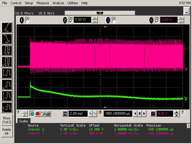
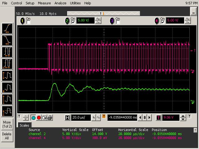
2. How to avoid the earth-shattering POP whenever I power it up?

Is there an RC circuit or similar with which to drive Shutdown or Mute such that there is no loud pop when powering up? So far, my debug setup consist of a full-up power source, such that the supply voltage has a step up, as opposed to the final product's unregulated transformer PS which is switched at the mains, which would, I assume, produce a slightly slower rate of rise - so that might make a difference. But trying to defeat it, I've experimented with hardwiring either Shutdown or Mute to the "off" state, powering up, then switching the respective input to the "on" state - and depending on which I do, I get the POP either when powering up, or controlling to "on" - I've not managed a POP-free startup.

Are Shutdown/Mute only intended for use with a (micro)controller setup which is powered up before the 3122, controls the 3122 power, and can therefore drive the high-active Mute high before the 3122 is powered up?

Or should this work with a single plainly-switched power supply, and I'm just doing it wrong? 

Is it just that my switch just to rough, and the smooth action of an RC circuit is needed?

  • Hi, achoox4,

    I am not sure I followed #1. Can you sketch it out and post a picture?

    For the pop, it is pretty good for this part. Is something upstream of this amp feeding it a transient?

    As for Power Supply Pumping, I am not sure if we ever published a formal app note, but there is a presentation on it here.

    -d2

  • Take the circuit from page 1 of the datasheet, just with the output filter values changed for 8 ohm SE according to table 3. (But I'll refer to the standard page 1 values below for easier reading.)

    Next, the Left Channel and Right Channel inputs are connected together to the same source (i.e. connected on the left side of the 1uF caps).

    In place of the two SE speakers, a single 4-ohm speaker is connected SE, with one pin to ground and the other pin to both filter circuits the same way the two individual speakers were.

    I.e. 2 identical amplifier halves are connected in parallel al the way from the single input to the single speaker.

    That works, right? Now, can I replace any of the duplicated components (and thus move the point were the two circuits connect closer to the IC) without causing problem?

    Examples: Can I remove one of the input 1uF caps and connec LIN and RIN pins together?

    Can I remove one of the 470uF output caps and connect the remaining 470 uF cap's left pin to both inductors and both 0.68uF caps? If so, can I also remove one of the inductors and connect ROUT and LOUT together?

    As for the pop, I've got nSD pulled high and Mute pulled low, and when I power up the entire circuit (including the pull-up, of course), I get a pop loud enough to fear for the speakers long-term no matter if my source is disconnected, off, paused (i.e. driving silence), or playing music. And as I said, if I do the equivalent of pushing the SD/mute override buttons on the EVM while powering up, I get the pop either right away or when I let go of the respective button (I forget now which of them doesn't affect the pop at all (probably mute) and which merely delays it (probably SD).

    Do you just recommend an already-on control circuit that drives these before the power comes up, or is there an accepted RC circuit for minimum pop?

  • Another question which I forgot: Except for surprising amounts of high-frequency background (quite audible during silence, but not at all noticeable with average-volume music), the sound in the current experimental setup is clean with both a 12V and 24V supply (stabilized or battery).

    Will the 3122D2 perform adequately with an unregulated rectified-AC (with 2000uF to 10000uF caps for smoothing ripple) supply or does it require regulation? This is intended to fully reap the benefits of needing no heatsink for the IC itself.

  • Hi Achoox4,


    Here are a couple of things to try for the pop issue. Could you first check to see what you have for the Cbyp capacitor? During startup or recovery from shutdown Cbyp determines the rate a which the amplifier starts up, which is a common contributor to the pop noise. The EVM is designed with a Cbyp value of 1uF for the best response to deal with the pop noise. Also, the input caps should match this value. The recommended capacitor type is low ESR ceramic or tantalum.

    In addition here is a useful appnote which gives an overview of the causes of pop noise as well as offer a solution to fix the issue:

    8345.TAS570X_Pop.pdf

    Let me know if this helps. Thanks!


    Regards,


    Brian Wang 

  • I'm pretty sure those caps are all 1uF as in the example/EVM schematic, but I will confirm.

    That app note is interesting, with Resetz on those parts taking the place of Mute on the TPA3122D2. But that does require a 3.3V (or similar) supply up already while AVCC and PVCC come up. (The second fix, for VR_ANA, doesn't apply to this part in any manner, does it?) Does that mean that a slow-rising RC "reset" on SD* is unlikely to work?

  • Hi Achoox4,


    It looks like for the TPA3122 a low at the mute pin keeps the device enabled and a high mutes it. The proposal from the app note would apply here as holding the mute pin low until 100us after the device is in a steady state (with VCC reaching its full level) so that you wont have glitches through the mute pin causing pops. The second fix doesnt apply to the TPA3122 as you said, for there is no pin for the internal regulated voltage. As long as the VCC applied to AVCC and PVCC simulaneously it should be good. Let me know if you get rid of the pop sound. Thanks!


    Regards,


    Brian Wang

  • I do have PVCC and AVCC on the same net, so they are simultaneous.

    As Mute is active-high, keeping it low initially (and later), which keeps the device enabled right from the start, is the default conditions (as opposed to overriding the pull-down with a momentary switch), and it pops.... Did you mean something different?

    But are glitches in these signals actually my problem?

    If I'm not mixing up my pop conditions (it's been a little while since I set this problem aside for later), then what I'm seeing is:

    -The active-high Mute doesn't remove the pop if I just hold high with AVCC/PVCC at startup, and I thought that was because VCC simply isn't high at first. But it is as high as VCC, so theoretically a logic high once logic is alive - but is that actually a glitch as VCC rises and things come alive, and a separate-supply pull-up (driven low to enable the device after a wait) would fix it?

    -The active-low shutdown held low removes the power-up pop, but it pops whenever I then deassert the low override - is that simply a glitch because I'm using a pushbutton which may bounce when I let go, and using an RC slow-rise would remove the glitch?

  • OK, I tried it three different ways with no more input signal glitches, and it doesn't help:

    -rising RC on SDn: power on, RC rises past threshold, pop.

    -falling RC on Mute (a longshot, I admit): power on, pop.

    -separate power on Mute: power on, pop.

    In other words:

    -Early Mute does nothing against the pop happening immediately upon power-up.

    -Shutdown, whenever it is deasserted, pops. (I did a slow enough RC to have a moment between applying power and seeing the voltage pass the threshold, so it's clearly happening at the threshold.)

    What I'd really like to know is this: Is this what you'd expect? When you power up the EVM with 12V or 24V, and with the SD button pushed, do you get a pop when you let go of SD? (Not with a $2 mylar speaker that only says "pzt" anyway, but at least a middle-of-the-road $10 TV speaker, if not a proper HiFi part.)

    Or is it all silent when you do the above, and thus I have a problem in my circuit? I gather that upon powering up, the PWM output instantly goes to 50% duty cycle, so the high-pass does nothing, but should the low-pass catch the highest harmonics of a square-wave rise? Or is this normal?

    If it is normal: Since the filters will take a moment (too long) to produce the pretense of a VCC/2 ground (or 0V center signal level), would it be possible to force the PWM circuit to a 0% duty cycle by pulling LIN/RIN to 0V or even lower at power-up, letting them rise softly to their usual DC level? What is the DC level at RIN/LIN?

  • Hi Achoox,

    I tested on the EVM powering up with 12V and 24V and did not hear the pop noise. Do you mind sending me a schematic of your circuit for me to take a look. 


    Regards,


    Brian Wang

  • Thanks for checking.

    I'm just using the EVM single-ended schematic from page 4 of the EVM manual at

    http://www.ti.com/lit/ug/slou214a/slou214a.pdf

    with the following changes/additions:

    In addition to C2/C8, there's a 2200uF across VCC/GND.

    C13 is 470uF.

    In accordance with the datasheet numbers for 8-ohm speakers, L1/L2 are 47uH and C9/C16 are 390nF.

    C10/C17 I optionally (i.e. tried both ways) change to 2200uF with the woofer or 100uF non-polarized with the bassless wideband speaker.

    The only other changes are between that schematic's pull resistor and pushbutton setups for SD/Mute vs. RC circuits vs. separate-supply pull-up, which have not affected the outcome.

    If/since this should just work, I can only assume I have a short or open somewhere. Oddly enough, I do hear the pop from all speakers (though only the bass moves enough to see it), i.e. both channels. Perhaps I made symmetric mistakes.

  • Hi Achoox4,


    I went back to do some testing on our EVM and actually found the pop sound as well! With Vcc about 15V or so there is an audible pop. So that's good, we're on the same page. In our case, this pop noise really comes down to the way the single ended filter works. Upon power up, the output DC level rises from zero torwards Vcc/2 (the DC of the 50% duty cycle PWM at at no input) fast enough that it passes through the DC blocking cap right before the speakers. In my case this would be a sudden 7 or 8V spike hitting the speakers which produces the pop. I have captured some scope shots to show this farther below.


    The first scope shot shows a zoom out of the PWM of the TPA3122 output (pink) and the point right between the DC blocking cap and the speaker (green). you see that at start up the sharp rise of DC level at the speaker which is from TPA3122 output DC flowing right through the DC blocking cap and then goes back to zero (what we expect normally with the blocking cap blocking the DC). The second shot is just a zoom in to see the rise due to the sudden change in DC.


    As you see from the comparison between BTL and SE, there is no DC blocking cap in BTL, since the differential outputs are on the same DC level. It is because BTL doesnt need this DC blocking cap, that BTL doesn't have the pop noise issue like in SE. Try it on your set up and see. I would suggest you to work with BTL, if you can that would great and you wont have the pop anymore.

     If you are sticking with SE, then we can try some solutions for de-pop. A common one is to bias the other end of the speaker (where the ground is) with a Vcc/2 voltage. As you can picture, when the DC rises suddenly towards Vcc/2 in our scenario, the DC accross the speaker witll now be negligible and thus suppressing the pop.

    There is another solution here in this app note also:

    1185.depop.pdf


    Hope this helps. Let me know how this goes. Thanks.


    Regards,


    Brian Wang 

  • I took out the series cap and attached a speaker as BTL (with no signal on the non-BTL input connection), power it up, and instead of the massive pop, got just the faintest soft tap sound, just like the scope shot above suggests. So that works nicely.

    I wouldn't mind at all using one whole TPA3122D2 per speaker in this manner, thereby also moving to less noisy parts of the power curves for the same output power.

    Producing a balanced signal, however, is another matter.

    1. IF/WHILE I don't have a balanced signal (e.g. because of the problems below, or because I end up having to use a single supply) then connecting unbalanced signal and ground(through 1uF) to the inputs of the TPA3122that is other wise set up as BTL, one half of the device would be wasted on producing a VCC/2 speaker ground with its 50% duty cycle PWM, but it would work, right? (I did not try this in case of unforeseen side effects.)

    2. I tried the DRV134 again, configured simply as shown in the datasheet, no resistors at the outputs, connected via the usual 1uF to the TPA3122 inputs. +/-12V supply. Just the like the first time I tried this, the DRV134 got hot enough to have been melted inside, while the TPA3122 and BTL speaker produced loud buzzing. Every schematic I've found for the DRV134 online is this same basic thing - what am I doing wrong?

    3. If or while the DRV134 continues to not work for me, will a circuit like in Figure 1 on this page (plus 1uF in series, I assume) work

    http://sound.westhost.com/articles/dwopa3.htm#balout

    thanks.

  • I tried the 2-opamp balanced output circuit as linked under (3) above, with 180 ohms at the outputs in series with the usual 1uF to RIN and LIN of the TPA3122, and I get very similar loud buzzing as with the DRV134 circuit, regardless of whether/what signal is applied.

    Is there some trick I don't know  to generating a balanced signal that the TPA3122 will accept?

  • Hi Achoox4,


    For your first question, the DC will be blocked by the DC blocking cap before the speakers. The Vcc/2 was only what happens during the very short time at power on that flows through, but that DC will return to zero (seen in the first plot on the previous post). Just to verify with you, you dont have the heat up problem that you did the first trial right? Now you just have a loud buzzing sound right? Did you test the performance of the DRV134 by itself and see if you notice any issues?


    Regards,


    Brian Wang

  • No, I did not try the DRV134 by itself.

    Connected via the usual 1uF to the TPA3122, the DRV134 gets quite hot and emits a burning smell.

  • Hi Achoox4,

    While we have not used the DRV134 directly in this application, I see no reason from looking at the d/s why this device wouldn't work in this application. Do you have the sense inputs shorted to the respective outputs? I could see problems if you haven't done that.

    -d2

  • Yes, the sense inputs were each connected to the appropriate output.

    The fact that the balanced output circuit (at the link 5 posts above this), built with an OPA2132, produced a similar noise and heat, makes me wonder if I'm missing something very fundamental.

    In all cases, I've got a +/-12V supply voltage from batteries, so there is no AC component in the supply that could cause trouble.Both the DRV134 and the OPA2132 have a max supply voltage larger then +/-12V.

    From the TPA3122D2's perspective, it's just a 0-24V supply, and the single-ended input signals' ground was referenced to the TPA3122 ground (i.e. -12V).

    For the DRV134 as well as the op-amp circuit,  the input signal (when connected) is referenced to the center ground (which is also present on a pin on the DRV134 but not on the op-amp IC).I assumed that for a "quiet" input, I could just tie the input to center ground (this is already accomplished by the 10k to center groud input load resistor in the op-amp circuit, so I left it at that) - am I possibly causing a great current draw there, because I the input is fighting against this voltage tie and I should have a large series resistor before the inputs instead?

    The differential outputs of either circuit are also centered around the center ground. The TPA3122D2 pulls its inputs, balanced or not, to whatever DC level it wants (0V, or close to it?). The 1uF series caps at the inputs should allow for this DC shift - is that not so?

  • If I give up and go back to the SE configuration, I would like to know if there is a definitive answer to my earlier questions about paralleling two TP3122 channels to drive one speaker:

    1. When using a single input signal for both channels, can I connect RIN and LIN and use a single series cap between them and the input signal?

    2. When using a single input signal for both channels and driving a single speaker, do I have to build the entire SE output circuit twice and connect left and right channel to the single speaker only at the point where separate speakers would otherwise connect (the right side of each channel's unlabeled cap in Figure 27 of the datasheet), or can I e.g. use a single SE series cap (the unlabeled cap in Figure 27 of the datasheet) with its left side connected to both channels' Lfilter-Cfilter nodes (thereby making those 2 node 1)?

  • Hi Achoox4,


    1. If you want to input a single signal into both channels, you will want to have coupling caps before each input, THEN connect the two channels. Or else you would be shorting the two channels together.


    2. For the output, you can connect the two outputs together, THEN have one LC filter. The tradeoff here is, now that single LC filter will need twice the current rating than each of the 2 LC filters you originally have. Although this is a reduction in component count, it could end up that the single LC filter is a larger and pricier solution than two individual ones.


    Hope this answers your question.


    Regards,


    Brian Wang

  • Brian Wang said:

    Hi Achoox4,


    1. If you want to input a single signal into both channels, you will want to have coupling caps before each input, THEN connect the two channels. Or else you would be shorting the two channels together.


    2. For the output, you can connect the two outputs together, THEN have one LC filter. The tradeoff here is, now that single LC filter will need twice the current rating than each of the 2 LC filters you originally have. Although this is a reduction in component count, it could end up that the single LC filter is a larger and pricier solution than two individual ones.


    Hope this answers your question.


    Regards,


    Brian Wang

    1. I guess if I shorted the inputs together, this would have their bias voltages drive against each other?

    2. That's even better. I suppose if I connected them in the middle of the LC fitler as I suggested, it would make an utter mess of the filter (paralleling the caps, and doing who knows what to the inductors), right?

  • Brian Wang said:

    2. For the output, you can connect the two outputs together, THEN have one LC filter. The tradeoff here is, now that single LC filter will need twice the current rating than each of the 2 LC filters you originally have. Although this is a reduction in component count, it could end up that the single LC filter is a larger and pricier solution than two individual ones.

    This did not work: I tried this first in my experimental setup, and some fraction of the time, it would power up working, but most of the time, it would produce no sound except a periodic ticking which subtly increased in volume over time. If I then dis- and reconnected the outputs, it would function. I tried it on a PCB setup (just to make sure it wasn't caused by a breadboard artifact) and got the same exact result, minus the possibility of disconnecting one output temporarily.

    (While testing the PCB version, I accidentally left the breadboard version powered up with no speaker. When I later rewired the breadboard to separate channels, it intermittently powered up making weird noises, and then the IC died altogether. New IC in breadboard showed  no such symptom, so I have to conclude continued operation while ticking damaged the IC.)

    Now, giving both outputs individual inductors and then connecting them (between the Ls and the Cs) together to the SE series cap works, but how do I adjust the L and C values given that the Ls from the 2 outputs come together but are not paralleled, while 2 Cs would just be paralleled. The  4 ohm speaker impedance is divided between the amp channels for power purposes, but how does the filter/do the filters see this? It's a woofer whose input signal will be filtered down above 200-300 Hz, so there's no harm in having rather too low an output filter frequency, but how do I even begin to calculate this?

    In both cases where there's a question of factoring for 1, 2, or 1/2 a component value (picking values for 8 ohm vs. 4 ohm, and how to count the Ls or the C), I'd want to err towards the lower frequency (because I have enough hiss already - not terrible, but I don't want even more). But how do each components' value increase/decrease into the output filter's frequency?

  • Hi Achoox4,


    Regarding the attempt to have both channels share one pair of LC filter, the problem could have been that there is a phase delay between the two inputs causing that difference to be reflected in the output. the two have to be completely in phase for this configuration. For LC selection I believe this application note is just the information you are looking for:

    7242.sloa119a.pdf


    Regards,


    Brian Wang